In physics and electrical engineering the reflection coefficient is a parameter that describes how much of a wave is reflected by an impedance discontinuity in the transmission medium. It is equal to the ratio of the amplitude of the reflected wave to the incident wave, with each expressed as phasors. For example, it is used in optics to calculate the amount of light that is reflected from a surface with a different index of refraction, such as a glass surface, or in an electrical transmission line to calculate how much of the electromagnetic wave is reflected by an impedance discontinuity. The reflection coefficient is closely related to the transmission coefficient. The reflectance of a system is also sometimes called a reflection coefficient.
In telecommunications, return loss is a measure in relative terms of the power of the signal reflected by a discontinuity in a transmission line or optical fiber. This discontinuity can be caused by a mismatch between the termination or load connected to the line and the characteristic impedance of the line. It is usually expressed as a ratio in decibels (dB);

In radio engineering and telecommunications, standing wave ratio (SWR) is a measure of impedance matching of loads to the characteristic impedance of a transmission line or waveguide. Impedance mismatches result in standing waves along the transmission line, and SWR is defined as the ratio of the partial standing wave's amplitude at an antinode (maximum) to the amplitude at a node (minimum) along the line.

A waveguide is a structure that guides waves by restricting the transmission of energy to one direction. Common types of waveguides include acoustic waveguides which direct sound, optical waveguides which direct light, and radio-frequency waveguides which direct electromagnetic waves other than light like radio waves.

In telecommunications, signal reflection occurs when a signal is transmitted along a transmission medium, such as a copper cable or an optical fiber. Some of the signal power may be reflected back to its origin rather than being carried all the way along the cable to the far end. This happens because imperfections in the cable cause impedance mismatches and non-linear changes in the cable characteristics. These abrupt changes in characteristics cause some of the transmitted signal to be reflected. In radio frequency (RF) practice this is often measured in a dimensionless ratio known as voltage standing wave ratio (VSWR) with a VSWR bridge. The ratio of energy bounced back depends on the impedance mismatch. Mathematically, it is defined using the reflection coefficient.

In radio engineering, an antenna or aerial is the interface between radio waves propagating through space and electric currents moving in metal conductors, used with a transmitter or receiver. In transmission, a radio transmitter supplies an electric current to the antenna's terminals, and the antenna radiates the energy from the current as electromagnetic waves. In reception, an antenna intercepts some of the power of a radio wave in order to produce an electric current at its terminals, that is applied to a receiver to be amplified. Antennas are essential components of all radio equipment.

In electrical engineering, impedance matching is the practice of designing or adjusting the input impedance or output impedance of an electrical device for a desired value. Often, the desired value is selected to maximize power transfer or minimize signal reflection. For example, impedance matching typically is used to improve power transfer from a radio transmitter via the interconnecting transmission line to the antenna. Signals on a transmission line will be transmitted without reflections if the transmission line is terminated with a matching impedance.
Twin lead cable is a two-conductor flat cable used as a balanced transmission line to carry radio frequency (RF) signals. It is constructed of two, stranded copper wires, or solid copper-clad steel wires. The wires are held a fixed distance apart by a plastic ribbon that is a good insulator at radio frequencies. It is also called ribbon cable. The uniform spacing of the wires is the key to the cable's function as a transmission line: Any abrupt change in spacing would cause some of the signal to reflect back toward the source, rather than passing through. The plastic also covers and insulates the wires. The name twin lead is most often used to refer specifically to 300 Ω (Ohm) ribbon cable, the most common type, but on occasion, twin lead is used to refer to any type of parallel wire line. Parallel wire line is available with several different values of characteristic impedance such as twin lead ribbon cable (300 Ω), window line, and open wire line or ladder line (500~650 Ω).

In electronics, electrical termination is the practice of ending a transmission line with a device that matches the characteristic impedance of the line. Termination prevents signals from reflecting off the end of the transmission line. Reflections at the ends of unterminated transmission lines cause distortion, which can produce ambiguous digital signal levels and misoperation of digital systems. Reflections in analog signal systems cause such effects as video ghosting, or power loss in radio transmitter transmission lines.

An antenna tuner is a passive electronic device inserted between a radio transmitter and its antenna. Its purpose is to optimize power transfer by matching the impedance of the radio to the signal impedance on the feedline to the antenna.
In electrical engineering, the input impedance of an electrical network is the measure of the opposition to current (impedance), both static (resistance) and dynamic (reactance), into a load network that is external to the electrical source network. The input admittance is a measure of the load network's propensity to draw current. The source network is the portion of the network that transmits power, and the load network is the portion of the network that consumes power.

A dummy load is a device used to simulate an electrical load, usually for testing purposes. In radio a dummy antenna is connected to the output of a radio transmitter and electrically simulates an antenna, to allow the transmitter to be adjusted and tested without radiating radio waves. In audio systems, a dummy load is connected to the output of an amplifier to electrically simulate a loudspeaker, allowing the amplifier to be tested without producing sound. Load banks are connected to electrical power supplies to simulate the supply's intended electrical load for testing purposes.

An antenna analyzer or in British aerial analyser is a device used for measuring the input impedance of antenna systems in radio electronics applications.
A radio transmitter or receiver is connected to an antenna which emits or receives the radio waves. The antenna feed system or antenna feed is the cable or conductor, and other associated equipment, which connects the transmitter or receiver with the antenna and makes the two devices compatible. In a radio transmitter, the transmitter generates an alternating current of radio frequency, and the feed system feeds the current to the antenna, which converts the power in the current to radio waves. In a radio receiver, the incoming radio waves excite tiny alternating currents in the antenna, and the feed system delivers this current to the receiver, which processes the signal.

A test probe is a physical device used to connect electronic test equipment to a device under test (DUT). Test probes range from very simple, robust devices to complex probes that are sophisticated, expensive, and fragile. Specific types include test prods, oscilloscope probes and current probes. A test probe is often supplied as a test lead, which includes the probe, cable and terminating connector.
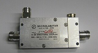
Power dividers and directional couplers are passive devices used mostly in the field of radio technology. They couple a defined amount of the electromagnetic power in a transmission line to a port enabling the signal to be used in another circuit. An essential feature of directional couplers is that they only couple power flowing in one direction. Power entering the output port is coupled to the isolated port but not to the coupled port. A directional coupler designed to split power equally between two ports is called a hybrid coupler.
In physics a null is a point in a field where the field quantity is zero as the result of two or more opposing quantities completely cancelling each other. The field may be scalar, vector or tensor in nature. Common situations where nulls arise are in the polar patterns of microphones and antennae, and nulls caused by reflections of waves.
Mismatch loss in transmission line theory is the amount of power expressed in decibels that will not be available on the output due to impedance mismatches and signal reflections. A transmission line that is properly terminated, that is, terminated with the same impedance as that of the characteristic impedance of the transmission line, will have no reflections and therefore no mismatch loss. Mismatch loss represents the amount of power wasted in the system. It can also be thought of as the amount of power gained if the system was perfectly matched. Impedance matching is an important part of RF system design; however, in practice there will likely be some degree of mismatch loss. In real systems, relatively little loss is due to mismatch loss and is often on the order of 1dB. According to Walter Maxwell mismatch does not result in any loss, except through the transmission line. This is because the signal reflected from the load is transmitted back to the source, where it is re-reflected due to the reactive impedance presented by the source, back to the load, until all of the signal's power is emitted or absorbed by the load.
A signal travelling along an electrical transmission line will be partly, or wholly, reflected back in the opposite direction when the travelling signal encounters a discontinuity in the characteristic impedance of the line, or if the far end of the line is not terminated in its characteristic impedance. This can happen, for instance, if two lengths of dissimilar transmission lines are joined.

Slotted lines are used for microwave measurements and consist of a movable probe inserted into a slot in a transmission line. They are used in conjunction with a microwave power source and usually, in keeping with their low-cost application, a low cost Schottky diode detector and VSWR meter rather than an expensive microwave power meter.