In radio engineering and telecommunications, standing wave ratio (SWR) is a measure of impedance matching of loads to the characteristic impedance of a transmission line or waveguide. Impedance mismatches result in standing waves along the transmission line, and SWR is defined as the ratio of the partial standing wave's amplitude at an antinode (maximum) to the amplitude at a node (minimum) along the line.

In radio engineering, an antenna or aerial is the interface between radio waves propagating through space and electric currents moving in metal conductors, used with a transmitter or receiver. In transmission, a radio transmitter supplies an electric current to the antenna's terminals, and the antenna radiates the energy from the current as electromagnetic waves. In reception, an antenna intercepts some of the power of a radio wave in order to produce an electric current at its terminals, that is applied to a receiver to be amplified. Antennas are essential components of all radio equipment.

A balun is an electrical device that allows balanced and unbalanced lines to be interfaced without disturbing the impedance arrangement of either line. A balun can take many forms and may include devices that also transform impedances but need not do so. Sometimes, in the case of transformer baluns, they use magnetic coupling but need not do so. Common-mode chokes are also used as baluns and work by eliminating, rather than rejecting, common mode signals.

In electronics, impedance matching is the practice of designing or adjusting the input impedance or output impedance of an electrical device for a desired value. Often, the desired value is selected to maximize power transfer or minimize signal reflection. For example, impedance matching typically is used to improve power transfer from a radio transmitter via the interconnecting transmission line to the antenna. Signals on a transmission line will be transmitted without reflections if the transmission line is terminated with a matching impedance.
Twin-lead cable is a two-conductor flat cable used as a balanced transmission line to carry radio frequency (RF) signals. It is constructed of two stranded or solid copper or copper-clad steel wires, held a precise distance apart by a plastic ribbon. The uniform spacing of the wires is the key to the cable's function as a transmission line; any abrupt changes in spacing would reflect some of the signal back toward the source. The plastic also covers and insulates the wires. It is available with several different values of characteristic impedance, the most common type is 300 ohm.

An antenna tuner is an electronic device insered into the feedline between a radio transmitter and its antenna. Its purpose is to optimize power transfer by matching the impedance of the radio to the impedance of the end of the feedline connecting the antenna to the transmitter.
The input impedance of an electrical network is the measure of the opposition to current (impedance), both static (resistance) and dynamic (reactance), into the load that is external to the electrical source network. The input admittance is a measure of the load network's propensity to draw current. The source network is the portion of the network that transmits power, and the load network is the portion of the network that consumes power.

The Beverage antenna or "wave antenna" is a long-wire receiving antenna mainly used in the low frequency and medium frequency radio bands, invented by Harold H. Beverage in 1921. It is used by amateur radio, shortwave listening, and longwave radio DXers and military applications.

A mast radiator is a radio mast or tower in which the metal structure itself is energized and functions as an antenna. This design, first used widely in the 1930s, is commonly used for transmitting antennas operating at low frequencies, in the LF and MF bands, in particular those used for AM radio broadcasting stations. The conductive steel mast is electrically connected to the transmitter. Its base is usually mounted on a nonconductive support to insulate it from the ground. A mast radiator is a form of monopole antenna.

A ‘T’-antenna, ‘T’-aerial, or flat-top antenna is a monopole radio antenna consisting of one or more horizontal wires suspended between two supporting radio masts or buildings and insulated from them at the ends. A vertical wire is connected to the center of the horizontal wires and hangs down close to the ground, connected to the transmitter or receiver. Combined, the top and vertical sections form a ‘T’ shape, hence the name. The transmitter power is applied, or the receiver is connected, between the bottom of the vertical wire and a ground connection. ‘T’-antennas are typically used in the VLF, LF, MF, and shortwave bands, and are widely used as transmitting antennas for amateur radio stations, and long wave and medium wave AM broadcasting stations. They can also be used as receiving antennas for shortwave listening.
A loop antenna is a radio antenna consisting of a loop or coil of wire, tubing, or other electrical conductor, that is usually fed by a balanced source or feeding a balanced load. Within this physical description there are two distinct types:

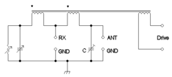
A network analyzer is an instrument that measures the network parameters of electrical networks. Today, network analyzers commonly measure s–parameters because reflection and transmission of electrical networks are easy to measure at high frequencies, but there are other network parameter sets such as y-parameters, z-parameters, and h-parameters. Network analyzers are often used to characterize two-port networks such as amplifiers and filters, but they can be used on networks with an arbitrary number of ports.

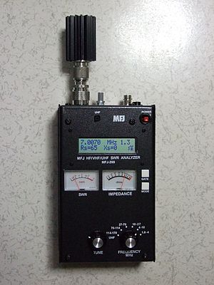
The standing wave ratio meter, SWR meter, ISWR meter, or VSWR meter measures the standing wave ratio (SWR) in a transmission line. The meter indirectly measures the degree of mismatch between a transmission line and its load. Electronics technicians use it to adjust radio transmitters and their antennas and feedlines to be impedance matched so they work together properly, and evaluate the effectiveness of other impedance matching efforts.
A radio transmitter or just transmitter is an electronic device which produces radio waves with an antenna. Radio waves are electromagnetic waves with frequencies between about 30 Hz and 300 GHz. The transmitter itself generates a radio frequency alternating current, which is applied to the antenna. When excited by this alternating current, the antenna radiates radio waves. Transmitters are necessary parts of all systems that use radio: radio and television broadcasting, cell phones, wireless networks, radar, two way radios like walkie talkies, radio navigation systems like GPS, remote entry systems, among numerous other uses.
A radio transmitter or receiver is connected to an antenna which emits or receives the radio waves. The antenna feed system or antenna feed is the cable or conductor, and other associated equipment, which connects the transmitter or receiver with the antenna and makes the two devices compatible. In a radio transmitter, the transmitter generates an alternating current of radio frequency, and the feed system feeds the current to the antenna, which converts the power in the current to radio waves. In a radio receiver, the incoming radio waves excite tiny alternating currents in the antenna, and the feed system delivers this current to the receiver, which processes the signal.
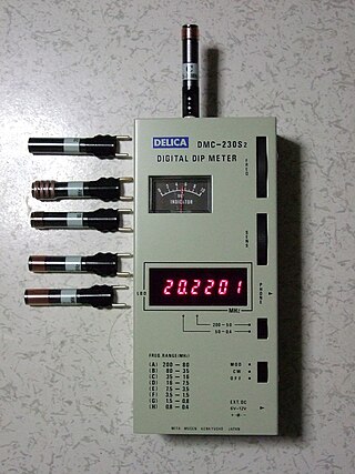
Grid dip oscillator (GDO), also called grid dip meter, gate dip meter, dip meter, or just dipper, is a type of electronic instrument that measures the resonant frequency of nearby unconnected radio frequency tuned circuits. It is a variable-frequency oscillator that circulates a small-amplitude signal through an exposed coil, whose electromagnetic field can interact with adjacent circuitry. The oscillator loses power when its coil is near a circuit that resonates at the same frequency. A meter on the GDO registers the amplitude drop, or "dip", hence the name.

A variety of types of electrical transformer are made for different purposes. Despite their design differences, the various types employ the same basic principle as discovered in 1831 by Michael Faraday, and share several key functional parts.
Radio-frequency (RF) engineering is a subset of electronic engineering involving the application of transmission line, waveguide, antenna and electromagnetic field principles to the design and application of devices that produce or use signals within the radio band, the frequency range of about 20 kHz up to 300 GHz.
A preselector is a name for an electronic device that connects between a radio antenna and a radio receiver. The preselector is a band-pass filter that blocks troublesome out-of-tune frequencies from passing through from the antenna into the radio receiver that otherwise would be directly connected to the antenna.

Slotted lines are used for microwave measurements and consist of a movable probe inserted into a slot in a transmission line. They are used in conjunction with a microwave power source and usually, in keeping with their low-cost application, a low cost Schottky diode detector and VSWR meter rather than an expensive microwave power meter.