Related Research Articles

A schematic, or schematic diagram, is a designed representation of the elements of a system using abstract, graphic symbols rather than realistic pictures. A schematic usually omits all details that are not relevant to the key information the schematic is intended to convey, and may include oversimplified elements in order to make this essential meaning easier to grasp, as well as additional organization of the information.
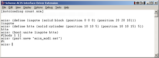
The 3D ACIS Modeler (ACIS) is a geometric modeling kernel developed by Spatial Corporation, part of Dassault Systemes. ACIS is used by many software developers in industries such as computer-aided design (CAD), computer-aided manufacturing (CAM), computer-aided engineering (CAE), architecture, engineering and construction (AEC), coordinate-measuring machine (CMM), 3D animation, and shipbuilding. ACIS provides software developers and manufacturers the underlying 3D modeling functionality.
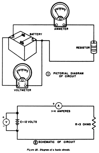
A circuit diagram is a graphical representation of an electrical circuit. A pictorial circuit diagram uses simple images of components, while a schematic diagram shows the components and interconnections of the circuit using standardized symbolic representations. The presentation of the interconnections between circuit components in the schematic diagram does not necessarily correspond to the physical arrangements in the finished device.

In integrated circuit design, integrated circuit (IC) layout, also known IC mask layout or mask design, is the representation of an integrated circuit in terms of planar geometric shapes which correspond to the patterns of metal, oxide, or semiconductor layers that make up the components of the integrated circuit. Originally the overall process was called tapeout, as historically early ICs used graphical black crepe tape on mylar media for photo imaging.
Schematic capture or schematic entry is a step in the design cycle of electronic design automation (EDA) at which the electronic diagram, or electronic schematic of the designed electronic circuit, is created by a designer. This is done interactively with the help of a schematic capture tool also known as schematic editor.
Place and route is a stage in the design of printed circuit boards, integrated circuits, and field-programmable gate arrays. As implied by the name, it is composed of two steps, placement and routing. The first step, placement, involves deciding where to place all electronic components, circuitry, and logic elements in a generally limited amount of space. This is followed by routing, which decides the exact design of all the wires needed to connect the placed components. This step must implement all the desired connections while following the rules and limitations of the manufacturing process.

CADSTAR is a Windows-based electronic design automation (EDA) software tool for designing and creating schematic diagrams and printed circuit boards (PCBs). It provides engineers with a tool for designing simple or complex, multilayer PCBs. CADSTAR spans schematic capture, variant management, placement, automatic and high-speed routing, signal integrity, power integrity, EMC analysis, design rule checks and production of manufacturing data.

TARGET 3001! is a CAD computer program for EDA and PCB design, developed by Ing.-Büro Friedrich in Germany. This software application has been available since 1992 and operates on Microsoft Windows. It supports the design of electronic schematics, PCBs, and device front panels. The software is available in English, German and French.

OrCAD Systems Corporation was a software company that made OrCAD, a proprietary software tool suite used primarily for electronic design automation (EDA). The software is used mainly by electronic design engineers and electronic technicians to create electronic schematics, and perform mixed-signal simulation and electronic prints for manufacturing printed circuit boards (PCBs). OrCAD was taken over by Cadence Design Systems in 1999 and was integrated with Cadence Allegro in 2005.

XCircuit is a schematic capture program for drawing publication-quality VLSI electrical circuit schematic diagrams and related figures. It's part of the Open Circuit Design tools. It's primarily intended for ULSI/VLSI IC design and not for PCB design, the latter though is still possible. XCircuit regards circuits as inherently hierarchical and can save circuits both in PostScript (.ps) and Ngspice (.cir) netlists file formats for further processing. The program compiles PostScript files from special template-labels specified by user.
CAD data exchange is a method of drawing data exchange used to translate between different computer-aided design (CAD) authoring systems or between CAD and other downstream CAx systems.

The layout versus schematic (LVS) is the class of electronic design automation (EDA) verification software that determines whether a particular integrated circuit layout corresponds to the original schematic or circuit diagram of the design.
CR-5000 is Zuken's EDA design suite for electronic systems and printed circuit boards aimed at the enterprise market. It was developed to address complex design needs that involve managing the complete development and manufacturing preparation process on an enterprise-wide scale. CR-5000 is made to facilitate the design of complex and high-speed boards, with features aimed at addressing challenges such as signal integrity and electromagnetic compatibility.
This page is a comparison of electronic design automation (EDA) software which is used today to design the near totality of electronic devices. Modern electronic devices are too complex to be designed without the help of a computer. Electronic devices may consist of integrated circuits (ICs), printed circuit boards (PCBs), field-programmable gate arrays (FPGAs) or a combination of them. Integrated circuits may consist of a combination of digital and analog circuits. These circuits can contain a combination of transistors, resistors, capacitors or specialized components such as analog neural networks, antennas or fuses.
Altium Designer (AD) is a PCB and electronic design automation software package for printed circuit boards. It is developed by American software company Altium Limited. Altium Designer was previously named under the "Protel" brand.

DipTrace is a proprietary software suite for electronic design automation (EDA) used for electronic schematic capture and printed circuit board layouts. DipTrace has four applications: schematic editor, PCB editor with built-in shape-based autorouter and 3D preview, component editor, and pattern editor.
FINE MEP is a BIM CAD software tool for building services engineering design, built on top of IntelliCAD. It provides full IFC support, according to the 2x3 IFC Standard. FINE BIM structure, enables a smart model shaping and high design accuracy, directly applied to the real 3D-building model and its building services. Not only the building elements, but also the components of the mechanical/electrical installations themselves are all intelligent objects carrying their own attributes and interacting among each other. MEP design is supported by specific CAD commands and further facilitated through sophisticated recognition and validation algorithms, providing a user-friendly modeling environment.
The FORAN system is an integrated CAD/CAM/CAE system developed by SENER for the design and production of practically any naval ship and offshore unit. It is a multidisciplinary and integrated system that can be used in all the ship design and production phases and disciplines. The System collects all the information in a single database. FORAN is mainly focused on the design of:
Pulsonix is an electronic design automation (EDA) software suite for schematic capture and PCB design. It is produced by WestDev, which is headquartered in Gloucestershire, England, with additional sales and distribution offices overseas. It was first released in 2001, and runs on Windows.
Reverse engineering of Printed circuit boards is the process of generating fabrication and design data for an existing circuit board, either closely or exactly replicating its functionality.
References
- ↑ "What is CAM?". ptc.com.
| | This electronics-related article is a stub. You can help Wikipedia by expanding it. |