
A schematic, or schematic diagram, is a designed representation of the elements of a system using abstract, graphic symbols rather than realistic pictures. A schematic usually omits all details that are not relevant to the key information the schematic is intended to convey, and may include oversimplified elements in order to make this essential meaning easier to grasp, as well as additional organization of the information.
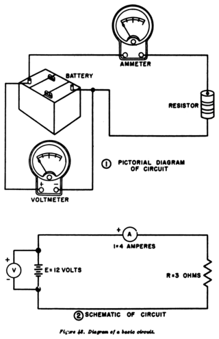
A circuit diagram is a graphical representation of an electrical circuit. A pictorial circuit diagram uses simple images of components, while a schematic diagram shows the components and interconnections of the circuit using standardized symbolic representations. The presentation of the interconnections between circuit components in the schematic diagram does not necessarily correspond to the physical arrangements in the finished device.

EAGLE is a scriptable electronic design automation (EDA) application with schematic capture, printed circuit board (PCB) layout, auto-router and computer-aided manufacturing (CAM) features. EAGLE stands for Easily Applicable Graphical Layout Editor and is developed by CadSoft Computer GmbH. The company was acquired by Autodesk Inc. in 2016 who announced to support the product up to 2026 only.

CADSTAR is a Windows-based electronic design automation (EDA) software tool for designing and creating schematic diagrams and printed circuit boards (PCBs). It provides engineers with a tool for designing simple or complex, multilayer PCBs. CADSTAR spans schematic capture, variant management, placement, automatic and high-speed routing, signal integrity, power integrity, EMC analysis, design rule checks and production of manufacturing data.

TARGET 3001! is a CAD computer program for EDA and PCB design, developed by Ing.-Büro Friedrich in Germany. It supports the design of electronic schematics, PCBs, and device front panels. It runs under Windows and is available in English, German and French.

OrCAD Systems Corporation was a software company that made OrCAD, a proprietary software tool suite used primarily for electronic design automation (EDA). The software is used mainly by electronic design engineers and electronic technicians to create electronic schematics, and perform mixed-signal simulation and electronic prints for manufacturing printed circuit boards (PCBs). OrCAD was taken over by Cadence Design Systems in 1999 and was integrated with Cadence Allegro in 2005.
The process of circuit design can cover systems ranging from complex electronic systems down to the individual transistors within an integrated circuit. One person can often do the design process without needing a planned or structured design process for simple circuits. Still, teams of designers following a systematic approach with intelligently guided computer simulation are becoming increasingly common for more complex designs. In integrated circuit design automation, the term "circuit design" often refers to the step of the design cycle which outputs the schematics of the integrated circuit. Typically this is the step between logic design and physical design.

XCircuit is a schematic capture program for drawing publication-quality VLSI electrical circuit schematic diagrams and related figures. It's part of the Open Circuit Design tools. It's primarily intended for ULSI/VLSI IC design and not for PCB design, the latter though is still possible. XCircuit regards circuits as inherently hierarchical and can save circuits both in PostScript (.ps) and Ngspice (.cir) netlists file formats for further processing. The program compiles PostScript files from special template-labels specified by user.
The term gEDA refers to two things:
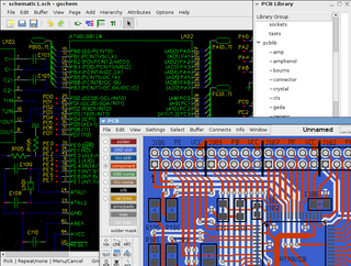
- A set of software applications used for electronic design released under the GPL. As such, gEDA is an ECAD or EDA application suite. gEDA is mostly oriented towards printed circuit board design. The gEDA applications are often referred to collectively as "the gEDA Suite".
- The collaboration of free software/open-source developers who work to develop and maintain the gEDA toolkit. The developers communicate via gEDA mailing lists, and have participated in the annual "Google Summer of Code" event as a single project. This collaboration is often referred to as "the gEDA Project".

NI Multisim is an electronic schematic capture and simulation program which is part of a suite of circuit design programs, along with NI Ultiboard. Multisim is one of the few circuit design programs to employ the original Berkeley SPICE based software simulation. Multisim was originally created by a company named Electronics Workbench Group, which is now a division of National Instruments. Multisim includes microcontroller simulation, as well as integrated import and export features to the printed circuit board layout software in the suite, NI Ultiboard.

KiCad is a free software suite for electronic design automation (EDA). It facilitates the design and simulation of electronic hardware. It features an integrated environment for schematic capture, PCB layout, manufacturing file viewing, ngspice-provided SPICE simulation, and engineering calculation. Tools exist within the package to create bill of materials, artwork, Gerber files, and 3D models of the PCB and its components.
Altium Limited is an American - Australian multinational software company that provides electronic design automation software to engineers who design printed circuit boards. Founded as Protel Systems Pty Ltd in Australia in 1985, the company has regional headquarters in the United States, Australia, China, Europe, and Japan. Its products are designed for use in a Microsoft Windows environment and used in industries such as automotive, aerospace, defense, and telecommunications. Its flagship product, Altium Designer, is a software for unified electronics design.
CR-5000 is Zuken's EDA design suite for electronics systems and printed circuit boards aimed at the enterprise market. It was developed to tackle complex design needs that involve managing the complete development and manufacturing preparation process on an enterprise-wide scale. CR-5000 offers relevant functionality for the design of complex and high-speed boards, addressing design challenges such as signal integrity and electromagnetic compatibility.

Altium Designer (AD) is a PCB and electronic design automation software package for printed circuit boards. It is developed by Australian software company Altium Limited.

PCB is a free and open-source software suite for electronic design automation (EDA) - for printed circuit boards (PCB) layout. It uses GTK+ for its GUI widgets.

DesignSpark PCB is a free electronic design automation software package for printed circuit boards. Although there is no charge for the software, the user must register with DesignSpark.com to unlock the program and it displays advertisements which must be acknowledged before the user can begin working.

DipTrace is a proprietary software suite for electronic design automation (EDA) used for electronic schematic capture and printed circuit board layouts. DipTrace has four applications: schematic capture editor, PCB layout editor with built-in shape-based autorouter and 3D preview, component editor, and pattern editor.

Pulsonix is an electronic design automation (EDA) software suite for schematic capture and PCB design. It is produced by WestDev, which is headquartered in Gloucestershire, England, with additional sales and distribution offices overseas. It was first released in 2001, and runs on Windows.
CircuitMaker is electronic design automation software for printed circuit board designs targeted at the hobby, hacker, and maker community. CircuitMaker is available as freeware, and the hardware designed with it may be used for commercial and non-commercial purposes without limitations. It is currently available publicly as version 2.0 by Altium Limited, with the first non-beta release on January 17, 2016.
EasyEDA is a web-based EDA tool suite that enables hardware engineers to design, simulate, share - publicly and privately - and discuss schematics, simulations and printed circuit boards. Other features include the creation of a bill of materials, Gerber files and pick and place files and documentary outputs in PDF, PNG and SVG formats.