
In optics, the refractive index of an optical medium is a dimensionless number that gives the indication of the light bending ability of that medium.
In telecommunications and electrical engineering, electrical length refers to the length of an electrical conductor in terms of the phase shift introduced by transmission over that conductor at some frequency.
The propagation constant of a sinusoidal electromagnetic wave is a measure of the change undergone by the amplitude and phase of the wave as it propagates in a given direction. The quantity being measured can be the voltage, the current in a circuit, or a field vector such as electric field strength or flux density. The propagation constant itself measures the change per unit length, but it is otherwise dimensionless. In the context of two-port networks and their cascades, propagation constant measures the change undergone by the source quantity as it propagates from one port to the next.
The wave impedance of an electromagnetic wave is the ratio of the transverse components of the electric and magnetic fields. For a transverse-electric-magnetic (TEM) plane wave traveling through a homogeneous medium, the wave impedance is everywhere equal to the intrinsic impedance of the medium. In particular, for a plane wave travelling through empty space, the wave impedance is equal to the impedance of free space. The symbol Z is used to represent it and it is expressed in units of ohms. The symbol η (eta) may be used instead of Z for wave impedance to avoid confusion with electrical impedance.

Coaxial cable, or coax is a type of electrical cable consisting of an inner conductor surrounded by a concentric conducting shield, with the two separated by a dielectric ; many coaxial cables also have a protective outer sheath or jacket. The term coaxial refers to the inner conductor and the outer shield sharing a geometric axis.
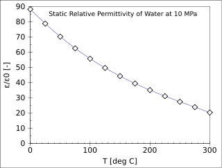
The relative permittivity is the permittivity of a material expressed as a ratio with the electric permittivity of a vacuum. A dielectric is an insulating material, and the dielectric constant of an insulator measures the ability of the insulator to store electric energy in an electrical field.
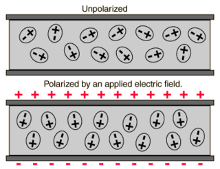
In electromagnetism, the absolute permittivity, often simply called permittivity and denoted by the Greek letter ε (epsilon), is a measure of the electric polarizability of a dielectric. A material with high permittivity polarizes more in response to an applied electric field than a material with low permittivity, thereby storing more energy in the material. In electrostatics, the permittivity plays an important role in determining the capacitance of a capacitor.

In the physical sciences, the wavenumber is the spatial frequency of a wave, measured in cycles per unit distance or radians per unit distance. It is analogous to temporal frequency, which is defined as the number of wave cycles per unit time or radians per unit time.
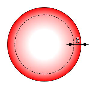
Skin effect is the tendency of an alternating electric current (AC) to become distributed within a conductor such that the current density is largest near the surface of the conductor and decreases exponentially with greater depths in the conductor. The electric current flows mainly at the "skin" of the conductor, between the outer surface and a level called the skin depth. Skin depth depends on the frequency of the alternating current; as frequency increases, current flow moves to the surface, resulting in less skin depth. Skin effect reduces the effective cross-section of the conductor and thus increases its effective resistance. Skin effect is caused by opposing eddy currents induced by the changing magnetic field resulting from the alternating current. At 60 Hz in copper, the skin depth is about 8.5 mm. At high frequencies the skin depth becomes much smaller.
In physics and engineering, a constitutive equation or constitutive relation is a relation between two physical quantities that is specific to a material or substance, and approximates the response of that material to external stimuli, usually as applied fields or forces. They are combined with other equations governing physical laws to solve physical problems; for example in fluid mechanics the flow of a fluid in a pipe, in solid state physics the response of a crystal to an electric field, or in structural analysis, the connection between applied stresses or loads to strains or deformations.
The velocity factor (VF), also called wave propagation speed or velocity of propagation, of a transmission medium is the ratio of the speed at which a wavefront passes through the medium, to the speed of light in vacuum. For optical signals, the velocity factor is the reciprocal of the refractive index.

Gaussian units constitute a metric system of physical units. This system is the most common of the several electromagnetic unit systems based on cgs (centimetre–gram–second) units. It is also called the Gaussian unit system, Gaussian-cgs units, or often just cgs units. The term "cgs units" is ambiguous and therefore to be avoided if possible: there are several variants of cgs with conflicting definitions of electromagnetic quantities and units.
An optical medium is material through which light and other electromagnetic waves propagate. It is a form of transmission medium. The permittivity and permeability of the medium define how electromagnetic waves propagate in it.

Microstrip is a type of electrical transmission line which can be fabricated with any technology where a conductor is separated from a ground plane by a dielectric layer known as the substrate. Microstrip lines are used to convey microwave-frequency signals.
Vacuum permittivity, commonly denoted ε0 is the value of the absolute dielectric permittivity of classical vacuum. Alternatively may be referred to as the permittivity of free space, the electric constant, or the distributed capacitance of the vacuum. It is an ideal (baseline) physical constant. Its CODATA value is:
The impedance of free space, Z0, is a physical constant relating the magnitudes of the electric and magnetic fields of electromagnetic radiation travelling through free space. That is, Z0 = |E|/|H|, where |E| is the electric field strength and |H| is the magnetic field strength. Its presently accepted value is
Dielectric loss quantifies a dielectric material's inherent dissipation of electromagnetic energy. It can be parameterized in terms of either the loss angleδ or the corresponding loss tangent tan δ. Both refer to the phasor in the complex plane whose real and imaginary parts are the resistive (lossy) component of an electromagnetic field and its reactive (lossless) counterpart.
The word electricity refers generally to the movement of electrons through a conductor in the presence of a potential difference or an electric field. The speed of this flow has multiple meanings. In everyday electrical and electronic devices, the signals travel as electromagnetic waves typically at 50%–99% of the speed of light, while the electrons themselves move much more slowly; see drift velocity and electron mobility.

A microwave cavity or radio frequency (RF) cavity is a special type of resonator, consisting of a closed metal structure that confines electromagnetic fields in the microwave region of the spectrum. The structure is either hollow or filled with dielectric material. The microwaves bounce back and forth between the walls of the cavity. At the cavity's resonant frequencies they reinforce to form standing waves in the cavity. Therefore, the cavity functions similarly to an organ pipe or sound box in a musical instrument, oscillating preferentially at a series of frequencies, its resonant frequencies. Thus it can act as a bandpass filter, allowing microwaves of a particular frequency to pass while blocking microwaves at nearby frequencies.
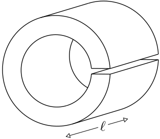
A loop-gap resonator (LGR) is an electromagnetic resonator that operates in the radio and microwave frequency ranges. The simplest LGRs are made from a conducting tube with a narrow slit cut along its length. The LGR dimensions are typically much smaller than the free-space wavelength of the electromagnetic fields at the resonant frequency. Therefore, relatively compact LGRs can be designed to operate at frequencies that are too low to be accessed using, for example, cavity resonators. These structures can have very sharp resonances making them useful for electron spin resonance (ESR) experiments, and precision measurements of electromagnetic material properties.


