Single-ended triode

Last updated
A SET tube audio amplifier. Audion-sterling-blue.jpg
A SET tube audio amplifier.

A single-ended triode (SET) is a vacuum tube electronic amplifier that uses a single triode to produce an output, in contrast to a push-pull amplifier which uses a pair of devices with antiphase inputs to generate an output with the wanted signals added and the distortion components subtracted. Single-ended amplifiers normally operate in Class A; push-pull amplifiers can also operate in Classes AB or B [ citation needed ] without excessive net distortion, due to cancellation.

Contents

The term single-ended triode amplifier is mainly used for output stages of audio power amplifiers. The phrase directly heated triode single-ended triode amplifier (abbreviated to DHT SET) is used when directly heated triodes are used.

There are also single-ended tetrode , beam tetrode/beam power tube/kinkless tetrode, and pentode amplifiers with the same functionality and similar circuitry; e.g. this Mullard design. [1]

Audio power amplifiers

A typical triode audio power amplifier will have a driver that provides voltage gain, coupled to a triode (like 2A3 and 300B) or a pentode or kinkless tetrode such as EL34 or KT88 connected as a triode, connected to the loudspeaker through an audio transformer in a common cathode arrangement. The triode is biased to Class A operation by applying a suitable negative bias voltage to its input control grid (see diagram), or by raising the cathode potential with biasing components.

Single-ended triode power stage.gif

In traditional SET amp, the direct current of output triode (from 30 mA for triode-strapped 6V6 to 250 mA for 6C33C) flows continuously through the primary winding of a transformer. This requires inserting a gap in the transformer core to prevent core saturation by DC current; adding a gap decreases primary inductance and limits bass response; the inductance and bass response can be restored by using a larger transformer than if the DC were not present.

An alternative schematic, parafeed amplifier, solves bandwidth problem by blocking direct current from output transformer (which does not need to be gapped, thus improving its bass response). Power supply is reconfigured into a constant current source, usually with a massive, high-inductance anode choke (gapped inductor), so there is little, if any, gain in cost and weight of magnetic components.

A stereo class A single-ended design with KT88 kinkless tetrodes which produces 15W of output power per channel, and 5W when triode-connected, is the Antique Sound Lab MG-SI15DT. [2] By comparison a pair of the same tubes in class AB push-pull claim to output about 50W at 1% distortion (higher powers at high distortion are quoted for guitar amplifiers).

Benefits

Drawbacks

Speaker matching

Historically, negative feedback in single ended pentode amplifiers was quite common (for example, the Mullard 3-3 design built around EL84 [1] ). Today negative feedback is less popular with SET amplifiers, with many having no overall feedback loop. Their frequency response, limited by transformer passband, is then modulated by irregularities in loudspeaker impedance. This, and the very low attainable power levels (3 Watts for 2A3 to 20 Watts for 6C33C), requires careful matching of amplifier to speakers; selection is usually limited to high-efficiency loudspeakers with a sensitivity exceeding 90 dB/Watt.

Audio quality

Single-ended triode (SET) amplifiers are considered a classic design among certain audiophiles and have achieved a cult status because of their alleged excellent midband performance (argued to be the most important part of the audio spectrum in music reproduction), "musicality" and "directness". This perceived high sonic quality is mainly attributed to the simplicity and minimalistic approach of the circuits involved and the triode amplifying tubes that are typically used.[ citation needed ]

On the other hand, the legitimacy of branding single-ended triode amplifiers as adequate for Hi-Fi purposes is debated, as from a technical standpoint, SET amplifiers are considered to be generally far inferior to subsequent (and more common) push-pull tube designs or solid-state amplifiers: [3] SET designs require output transformers which are able to cope with a strong DC component in the signal, which causes them to have worse performance in regard to frequency response, distortion and efficiency (although the latter is not generally a priority for most SET enthusiasts, or audiophiles in general). Furthermore, as SET amplifiers have a relatively high output impedance, it is hard to couple them effectively to a loudspeaker which hasn't been designed especially to be driven by a high output impedance amplifier, as this will cause the amplifier to be much more sensitive to the loudspeaker's impedance characteristics across the spectrum, resulting in coloration.

In general, the configuration will usually provide higher measured distortion performance compared to high feedback amplifiers. [3] This distortion is predominantly second harmonic which is not unpleasant to the ear (the second harmonic for an A on the musical scale at 440 Hz is 880 Hz which is, obviously, also an A i.e., the same note just an octave higher)[ citation needed ], but by definition their high THD figures make SET amplifiers inaccurate. In a push pull amplifier this second harmonic distortion is cancelled in the output transformer. Several percent THD is not unusual at full power output, but will be much lower at normal music levels. Some builders and users have concluded that while global feedback reduces distortion across the harmonic range, it also reduces the dramatic dynamics associated with a SET amplifier and the highly efficient speaker needed to enjoy a low power amplifier, but this is also strongly debated.

Apart from the field of hi-fi amplification, SET amplifiers are well regarded by some in the guitar world precisely due to their distortion characteristics, which may considered desirable in the context of musical instrument amplification, as their aim isn't accuracy but expressiveness and harmonic complexity. [4]

Estimating power output for a Class A1 amplifier from valve specifications

In class A, in order to produce a full sine wave, the tube must be exactly half-way on. Therefore, the maximum current swing is +/- 50%. No actual amplifier will ever achieve this.

Obtain the following parameters:

Compute maximum theoretical power output by P[ot] = Pa / 2.

While the valve can be driven all the way to shut-off fairly easily, the maximum current will be limited by the internal resistance of the valve as the grid reaches the voltage of the cathode and is not impeding electron flow. For this reason, valves that have a low Rp can yield more power in class A1 than other valves with similar Pa ratings.

Next, compute P[o] = P[ot] * (1 - Rp/Rl) to obtain an estimate of the maximum obtainable output power.

Deduct 10% from this figure to account for the relatively heavy distortion encountered as the valve approaches cut-off.

Class A2

Class A2 amplifiers can overcome a high Rp by driving the grid positive with respect to the cathode. Because this makes the grid a secondary anode, it too will draw current from the cathode while accelerating the remaining electrons towards the plate. Grid currents can place extreme demands on the driving circuitry, sometimes requiring as much as 8 watts input for larger tubes such as the 211.

See also

Related Research Articles

<span class="mw-page-title-main">Amplifier</span> Electronic device/component that increases the strength of a signal

An amplifier, electronic amplifier or (informally) amp is an electronic device that can increase the magnitude of a signal. It is a two-port electronic circuit that uses electric power from a power supply to increase the amplitude of a signal applied to its input terminals, producing a proportionally greater amplitude signal at its output. The amount of amplification provided by an amplifier is measured by its gain: the ratio of output voltage, current, or power to input. An amplifier is defined as a circuit that has a power gain greater than one.

A tetrode is a vacuum tube having four active electrodes. The four electrodes in order from the centre are: a thermionic cathode, first and second grids, and a plate. There are several varieties of tetrodes, the most common being the screen-grid tube and the beam tetrode. In screen-grid tubes and beam tetrodes, the first grid is the control grid and the second grid is the screen grid. In other tetrodes one of the grids is a control grid, while the other may have a variety of functions.
<span class="mw-page-title-main">Valve amplifier</span> Type of electronic amplifier

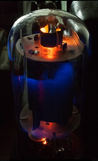
A valve amplifier or tube amplifier is a type of electronic amplifier that uses vacuum tubes to increase the amplitude or power of a signal. Low to medium power valve amplifiers for frequencies below the microwaves were largely replaced by solid state amplifiers in the 1960s and 1970s. Valve amplifiers can be used for applications such as guitar amplifiers, satellite transponders such as DirecTV and GPS, high quality stereo amplifiers, military applications and very high power radio and UHF television transmitters.

<span class="mw-page-title-main">Control grid</span> Electrode used to control electron flow within a vacuum tube

The control grid is an electrode used in amplifying thermionic valves such as the triode, tetrode and pentode, used to control the flow of electrons from the cathode to the anode (plate) electrode. The control grid usually consists of a cylindrical screen or helix of fine wire surrounding the cathode, and is surrounded in turn by the anode. The control grid was invented by Lee De Forest, who in 1906 added a grid to the Fleming valve to create the first amplifying vacuum tube, the Audion (triode).

<span class="mw-page-title-main">Push–pull output</span> Type of electronic circuit

A push–pull amplifier is a type of electronic circuit that uses a pair of active devices that alternately supply current to, or absorb current from, a connected load. This kind of amplifier can enhance both the load capacity and switching speed.

The Williamson amplifier is a four-stage, push-pull, Class A triode-output valve audio power amplifier designed by D. T. N. Williamson during World War II. The original circuit, published in 1947 and addressed to the worldwide do it yourself community, set the standard of high fidelity sound reproduction and served as a benchmark or reference amplifier design throughout the 1950s. The original circuit was copied by hundreds of thousands amateurs worldwide. It was an absolute favourite on the DIY scene of the 1950s, and in the beginning of the decade also dominated British and North American markets for factory-assembled amplifiers.

<span class="mw-page-title-main">Beam tetrode</span>

A beam tetrode, sometimes called a beam power tube, is a type of vacuum tube or thermionic valve that has two grids and forms the electron stream from the cathode into multiple partially collimated beams to produce a low potential space charge region between the anode and screen grid to return anode secondary emission electrons to the anode when the anode potential is less than that of the screen grid. Beam tetrodes are usually used for power amplification, from audio frequency to radio frequency. The beam tetrode produces greater output power than a triode or pentode with the same anode supply voltage. The first beam tetrode marketed was the Marconi N40, introduced in 1935. Beam tetrodes manufactured and used in the 21st century include the 4CX250B, KT66 and variants of the 6L6.

<span class="mw-page-title-main">Pentode</span> Vacuum tube with five electrodes

A pentode is an electronic device having five electrodes. The term most commonly applies to a three-grid amplifying vacuum tube or thermionic valve that was invented by Gilles Holst and Bernhard D.H. Tellegen in 1926. The pentode was developed from the screen-grid tube or shield-grid tube by the addition of a grid between the screen grid and the plate. The screen-grid tube was limited in performance as an amplifier due to secondary emission of electrons from the plate. The additional grid is called the suppressor grid. The suppressor grid is usually operated at or near the potential of the cathode and prevents secondary emission electrons from the plate from reaching the screen grid. The addition of the suppressor grid permits much greater output signal amplitude to be obtained from the plate of the pentode in amplifier operation than from the plate of the screen-grid tube at the same plate supply voltage. Pentodes were widely manufactured and used in electronic equipment until the 1960s to 1970s, during which time transistors replaced tubes in new designs. During the first quarter of the 21st century, a few pentode tubes have been in production for high power radio frequency applications, musical instrument amplifiers, home audio and niche markets.

<span class="mw-page-title-main">EL34</span> Vacuum tube (valve)

The EL34 is a thermionic vacuum tube of the power pentode type. The EL34 was introduced in 1955 by Mullard, who were owned by Philips. The EL34 has an octal base and is found mainly in the final output stages of audio amplification circuits; it was also designed to be suitable as a series regulator by virtue of its high permissible voltage between heater and cathode and other parameters. The American RETMA tube designation number for this tube is 6CA7. The USSR analog was 6P27S.

A valve audio amplifier (UK) or vacuum tube audio amplifier (US) is a valve amplifier used for sound reinforcement, sound recording and reproduction.
<span class="mw-page-title-main">Valve transmitters</span>

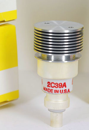
Most high power transmitter amplifiers are of valve construction because of the high power required.

The KT88 is a beam tetrode/kinkless tetrode vacuum tube for audio amplification.

Ultra-linear electronic circuits are those used to couple a tetrode or pentode vacuum-tube to a load.
<span class="mw-page-title-main">Valve RF amplifier</span> Device for electrically amplifying the power of an electrical radio frequency signal

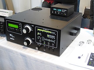
A valve RF amplifier or tube amplifier (U.S.) is a device for electrically amplifying the power of an electrical radio frequency signal.

Technical specifications and detailed information on the valve audio amplifier, including its development history.

Circlotron valve amplifier is a type of power amplifier utilizing symmetrical cathode-coupled bridge layout of the output stage. Original circlotrons of 1950s used output transformers to couple relatively high output impedance of vacuum tubes to low-impedance loudspeakers. Circlotron architecture, easily scalable, was eventually adapted to operate without output transformers, and present-day commercially produced circlotron models are of output transformerless (OTL) type.

<span class="mw-page-title-main">Plate detector (radio)</span>

In electronics, a plate detector is a vacuum tube circuit in which an amplifying tube having a control grid is operated in a non-linear region of its grid voltage versus plate current transfer characteristic, usually near plate current cutoff, to demodulate amplitude modulated carrier signal. This differs from the grid leak detector, which utilizes the non-linearity of the grid voltage versus grid current characteristic for demodulation. It also differs from the diode detector, which is a two-terminal device.

<span class="mw-page-title-main">Tube sound</span> Characteristic quality of sounds from vacuum tube amplifiers

Tube sound is the characteristic sound associated with a vacuum tube amplifier, a vacuum tube-based audio amplifier. At first, the concept of tube sound did not exist, because practically all electronic amplification of audio signals was done with vacuum tubes and other comparable methods were not known or used. After introduction of solid state amplifiers, tube sound appeared as the logical complement of transistor sound, which had some negative connotations due to crossover distortion in early transistor amplifiers. However, solid state amplifiers have been developed to be flawless and the sound is later regarded neutral compared to tube amplifiers. Thus the tube sound now means 'euphonic distortion.' The audible significance of tube amplification on audio signals is a subject of continuing debate among audio enthusiasts.

A Virtual Valve Amplifier (VVA) is software algorithm designed and sold by Diamond Cut Productions, Inc. for simulating the sound of various valve amplifier designs. It can be found within their DC8 and Forensics8 software programs.

References

  1. 1 2 "Mullard Single Ended EL84 Tube Amplifier"
  2. Product Review - Antique Sound Lab MG-SI15DT Single Ended Integrated Tube Amplifier - January, 2001
  3. 1 2 Elliott, Rod. "Valve (Vacuum Tube) Amplifier Design Considerations - ESP (Elliott Sound Products)".
  4. "What Do the Terms "Push-Pull" and "Single-Ended" Mean?". Archived from the original on 2013-01-24.

Further reading