Solenoid (engineering)

Last updated

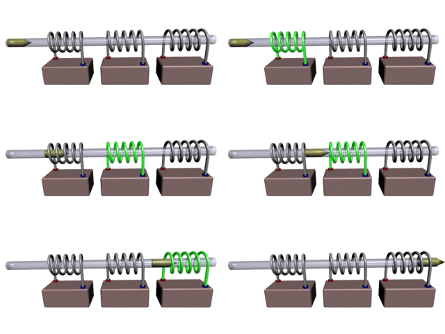
In engineering, a solenoid is a device that converts electrical energy to mechanical energy, using an electromagnet formed from a coil of wire. The device creates a magnetic field [1] from electric current, and uses the magnetic field to create linear motion. [2] [3] [4] In electromagnetic technology, a solenoid is an actuator assembly with a sliding ferromagnetic plunger inside the coil. Without power, the plunger extends for part of its length outside the coil; applying power pulls the plunger into the coil. Electromagnets with fixed cores are not considered solenoids. In simple terms, a solenoid converts electrical energy into mechanical work. Typically, it has a multiturn coil of magnet wire surrounded by a frame, which is also a magnetic flux carrier to enhance its efficiency. In engineering, the term may also refer to a variety of transducer devices that convert energy into linear motion, more sophisticated than simple two–position actuators. [5] The term "solenoid" also often refers to a solenoid valve, an integrated device containing an electromechanical solenoid which actuates either a pneumatic or hydraulic valve, or a solenoid switch, which is a specific type of relay that internally uses an electromechanical solenoid to operate an electrical switch; for example, an automobile starter solenoid or linear solenoid. Solenoid bolts, a type of electromechanical locking mechanism, also exist.

Contents

Applications

Electromechanical solenoid

A 1920 explanation of a commercial solenoid used as an electromechanical actuator Commercial Solenoid Dawes 1920.png
A 1920 explanation of a commercial solenoid used as an electromechanical actuator

Electromechanical solenoids consist of an electromagnetically inductive coil, wound around a movable steel or iron slug (termed the armature). The coil is shaped such that the armature can be moved in and out of the space in the center of the coil, altering the coil's inductance and thereby becoming an electromagnet. The movement of the armature is used to provide a mechanical force to some mechanism, such as controlling a solenoid valve. Although typically weak over anything but very short distances, solenoids may be controlled directly by a controller circuit, and thus have very quick reaction times.

The force applied to the armature is proportional to the change in inductance of the coil with respect to the change in position of the armature and the current flowing through the coil (see Faraday's law of induction). The force applied to the armature will always move the armature in a direction that increases the coil's inductance.

Electromechanical solenoids are commonly seen in electronic paintball markers, pinball machines, dot matrix printers, and fuel injectors. Some residential doorbells make use of electromechanical solenoids, whereby electrification of the coil causes the armature to strike metal chime bars. [6]

Push and pull solenoids

Push and pull solenoids are common catalog items, usually in a tubular construction. They consist of a bobbin-wound coil, steel plunger, cylindrical case and end pieces, one of which is a stator pole. Each type is similar to the other in construction except that the pull type has means for attaching to the plunger and pulls the attached load toward the solenoid. The push type has a push-pin projecting out of the solenoid to push the load away from the solenoid. Magnetically they are the same; i.e., internally the magnetic field attracts the plunger toward the stator pole piece. Most solenoids do not use magnetic repulsion between the magnetic pole and plunger to do the pushing except in rare instances. Some permanent magnet types operate by simultaneous attraction and repulsion of the plunger in the same direction in order to actuate (and are bi-directional by reversing the coil's electrical polarity). Common push or pull solenoids move in one direction only upon being energized. A spring or other means is required to move the plunger to its de-energized position. Other constructions utilize a C- or D-shaped frame of bent flat steel and the coil may be visible. The efficiency of these types are due to their steel outer frames which enclose the magnetic flux around the coil (end to end) to focus the flux at the air gap between the plunger and stator pole.

Proportional solenoid

Included in this category of solenoids are the uniquely designed magnetic circuits that effect analog positioning of the solenoid plunger or armature as a function of coil current. These solenoids, whether axial or rotary, employ a flux carrying geometry that both produces a high starting force (torque), and has a section that quickly begins to saturate magnetically. The resulting force (torque) profile as the solenoid progresses through its operational stroke is nearly flat or descends from a high to a lower value. The solenoid can be useful for positioning, stopping mid-stroke, or for low velocity actuation; especially in a closed loop control system. A uni-directional solenoid would actuate against an opposing force or a dual solenoid system would be self cycling. The proportional concept is more fully described in SAE publication 860759 (1986).

Focusing of the magnetic field and its attendant flux metering, as illustrated in the SAE paper, is required to produce a high starting force at the start of the solenoid stroke and to maintain a level or declining force as the solenoid moves through its displacement range. This is quite contrary to that experienced with normal diminishing air gap types of solenoids. The focusing of the magnetic field to the working air gap initially produces a high mmf (ampere turns) and relatively low flux level across the air gap. This high product of mmf x flux (read energy) produces a high starting force. As the plunger is incremented (ds) the energy of motion, F∙ds, is extracted from the air gap energy. Inherent with the plunger increment of motion, the air gap permeance increases slightly, the magnetic flux increases, the mmf across the air gap decreases slightly; all of which results in maintaining a high product of mmf x flux. Because of the increased flux level a rise in ampere-turns drops elsewhere in the ferrous circuit (predominately in the pole geometry) causes the reduction of air gap ampere-turns and, therefore, the reduced potential energy of the field at the air gap. Further incrementing of the plunger causes a continuing decrease of the solenoid force thus creating an ideal condition for motion control as controlled by the current to the solenoid coil. The aforementioned pole geometry, having a linearly changing path area, produces a nearly linear change in force. An opposing spring force or a dual ended solenoid (two coils) allows over and back motion control. Closed loop control improves the linearity and stiffness of the system.

Rotary solenoid

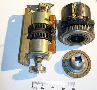
The rotary solenoid is an electromechanical device used to rotate a ratcheting mechanism when power is applied. These were used in the 1950s for rotary snap-switch automation in electromechanical controls. Repeated actuation of the rotary solenoid advances the snap-switch forward one position. Two rotary actuators on opposite ends of the rotary snap-switch shaft, can advance or reverse the switch position.

The rotary solenoid has a similar appearance to a linear solenoid, except that the armature core is mounted in the center of a large flat disk, with three inclined raceways coined into the underside of the disk. These grooves align with raceways on the solenoid body, separated by ball bearings in the races.

When the solenoid is activated, the armature core is magnetically attracted toward the stator pole, and the disk rotates on the ball bearings in the races as it moves towards the coil body. When power is removed, a spring on the disk rotates it back to its starting position both rotationally and axially.

The rotary solenoid was invented in 1944 by George H. Leland, of Dayton, Ohio, to provide a more reliable and shock/vibration tolerant release mechanism for air-dropped bombs. Previously used linear (axial) solenoids were prone to inadvertent releases. U.S. Patent number 2,496,880 describes the electromagnet and inclined raceways that are the basis of the invention. Leland's engineer, Earl W. Kerman, was instrumental in developing a compatible bomb release shackle that incorporated the rotary solenoid. Bomb shackles of this type are found in a B-29 aircraft fuselage on display at the National Museum of the USAF in Dayton, Ohio. It was a 1-inch diameter version of the Leland solenoid that served as the camera shutter for Mariner-4's fly-by of Mars in July 1965. Solenoids of this variety continue to be used in countless modern applications and are still manufactured under Leland's original brand "Ledex", now owned by Johnson Electric.

Appearing on the market in the 1980s, the solely rotary solenoid with a balanced 3-lobed iron vane rotor offered improved vibration isolation by eliminating the axial motion of the rotor. This device allowed proportional, quiet positioning as well as a rapid rotation for uses such as mail sorters and conveyor gating. Then followed a permanent magnet rotor version (U.S. Patent 5,337,030; 1994 ) that provided rapid, electrical, bi-directional rotation.

Rotary voice coil

A rotary voice coil is a rotational version of a solenoid. Typically the fixed magnet is on the outside, and the coil part moves in an arc controlled by the current flow through the coils. Rotary voice coils are widely employed in devices such as disk drives.[ citation needed ] The working part of a moving coil meter is also a type of rotary voice coil that pivots around the pointer axis, a hairspring is usually used to provide a weak nearly linear restoring force.

Pneumatic solenoid valve

Solenoid of a pneumatic valve Solenoid coil of a pneumatic valve.jpg
Solenoid of a pneumatic valve

A pneumatic solenoid valve is a switch for routing air to any pneumatic device, usually an actuator, allowing a relatively small signal to control a large device. It is also the interface between electronic controllers and pneumatic systems.[ citation needed ]

Hydraulic solenoid valve

Hydraulic solenoid valves are in general similar to pneumatic solenoid valves except that they control the flow of hydraulic fluid (oil), often at around 3000 psi (210 bar, 21 MPa, 21 MN/m2). Hydraulic machinery uses solenoids to control the flow of oil to rams or actuators. Solenoid-controlled valves are often used in irrigation systems, where a relatively weak solenoid opens and closes a small pilot valve, which in turn activates the main valve by applying fluid pressure to a piston or diaphragm that is mechanically coupled to the main valve. Solenoids are also in everyday household items such as washing machines to control the flow and amount of water into the drum.

Transmission solenoids control fluid flow through an automatic transmission and are typically installed in the transmission valve body.

Automobile starter solenoid

In a car or truck, the starter solenoid is part of an automobile engine's ignition system. The starter solenoid receives a large electric current from the car battery and a small electric current from the ignition switch. When the ignition switch is turned on (i.e. when the key is turned to start the car), the small electric current forces the starter solenoid to close a pair of heavy contacts, thus relaying the large electric current to the starter motor. This is a type of relay.

Starter solenoids can also be built into the starter itself, often visible on the outside of the starter. If a starter solenoid receives insufficient power from the battery, it will fail to start the motor and may produce a rapid, distinctive "clicking" or "clacking" sound. This can be caused by a low or dead battery, by corroded or loose connections to the battery, or by a broken or damaged positive (red) cable from the battery. Any of these will result in some power to the solenoid, but not enough to hold the heavy contacts closed, so the starter motor itself never spins, and the engine fails to start.

See also

Related Research Articles

<span class="mw-page-title-main">Relay</span> Electrically-operated switch

A relay is an electrically operated switch. It consists of a set of input terminals for a single or multiple control signals, and a set of operating contact terminals. The switch may have any number of contacts in multiple contact forms, such as make contacts, break contacts, or combinations thereof.

<span class="mw-page-title-main">Electric motor</span> Machine that converts electrical energy into mechanical energy

An electric motor is an electrical machine that converts electrical energy into mechanical energy. Most electric motors operate through the interaction between the motor's magnetic field and electric current in a wire winding to generate force in the form of torque applied on the motor's shaft. An electric generator is mechanically identical to an electric motor, but operates in reverse, converting mechanical energy into electrical energy.

<span class="mw-page-title-main">Electromagnet</span> Magnet created with an electric current

An electromagnet is a type of magnet in which the magnetic field is produced by an electric current. Electromagnets usually consist of wire wound into a coil. A current through the wire creates a magnetic field which is concentrated in the hole in the center of the coil. The magnetic field disappears when the current is turned off. The wire turns are often wound around a magnetic core made from a ferromagnetic or ferrimagnetic material such as iron; the magnetic core concentrates the magnetic flux and makes a more powerful magnet.

A transducer is a device that converts energy from one form to another. Usually a transducer converts a signal in one form of energy to a signal in another. Transducers are often employed at the boundaries of automation, measurement, and control systems, where electrical signals are converted to and from other physical quantities. The process of converting one form of energy to another is known as transduction.

<span class="mw-page-title-main">Coilgun</span> Artillery using coils to electromagnetically propel a projectile

A coilgun is a type of mass driver consisting of one or more coils used as electromagnets in the configuration of a linear motor that accelerate a ferromagnetic or conducting projectile to high velocity. In almost all coilgun configurations, the coils and the gun barrel are arranged on a common axis. A coilgun is not a rifle as the barrel is smoothbore.

An actuator is a component of a machine that produces force, torque, or displacement, usually in a controlled way, when an electrical, pneumatic or hydraulic input is supplied to it in a system. An actuator converts such an input signal into the required form of mechanical energy. It is a type of transducer. In simple terms, it is a "mover".

<span class="mw-page-title-main">Linear induction motor</span> Type of linear motor

A linear induction motor (LIM) is an alternating current (AC), asynchronous linear motor that works by the same general principles as other induction motors but is typically designed to directly produce motion in a straight line. Characteristically, linear induction motors have a finite primary or secondary length, which generates end-effects, whereas a conventional induction motor is arranged in an endless loop.

<span class="mw-page-title-main">Solenoid valve</span> Electromechanical valve

A solenoid valve is an electromechanically operated valve.

<span class="mw-page-title-main">Linear actuator</span> Actuator that creates motion in a straight line

A linear actuator is an actuator that creates linear motion, in contrast to the circular motion of a conventional electric motor. Linear actuators are used in machine tools and industrial machinery, in computer peripherals such as disk drives and printers, in valves and dampers, and in many other places where linear motion is required. Hydraulic or pneumatic cylinders inherently produce linear motion. Many other mechanisms are used to generate linear motion from a rotating motor.

<span class="mw-page-title-main">Armature (electrical)</span> Power-producing component of an electric machine

In electrical engineering, the armature is the winding of an electric machine which carries alternating current. The armature windings conduct AC even on DC machines, due to the commutator action or due to electronic commutation, as in brushless DC motors. The armature can be on either the rotor or the stator, depending on the type of electric machine.

A pneumatic control valve actuator converts energy into mechanical motion. The motion can be rotary or linear, depending on the type of actuator.

A variable force solenoid (VFS) is an electro-hydraulic device that controls pressure proportionally or inversely proportionally to a signal obtained from the on-board controller of a powertrain. A low flow VFS is used as a signal level devices for transmission line pressure control or application of clutches. A high flow VFS controls line pressure directly or are used for direct shift clutch control. A VFS is a type of Transmission Solenoid. One or more VFS can be used in an automatic transmission or installed in an automatic transmission valve body.

<span class="mw-page-title-main">Electromagnetic clutch</span> Clutch that operates electrically but transmits torque mechanically

Electromagnetic clutches operate electrically but transmit torque mechanically. This is why they used to be referred to as electro-mechanical clutches. Over the years, EM became known as electromagnetic versus electro-mechanical, referring more about their actuation method versus physical operation. Since the clutches started becoming popular over 60 years ago, the variety of applications and clutch designs has increased dramatically, but the basic operation remains the same today.

The stop action magnet, usually abbreviated to SAM, is an electromagnetic device used for the control of pipe organs and virtual pipe organs, and forms part of the organ's combination action. On a classical organ the device may be referred to as a drawstop solenoid. The SAM can be considered an electrical relay, the difference being that the SAM also has a drawknob or a tab, which enables it to be operated manually as well as electrically.

The Camcon binary actuator is an electronically-controlled electromagnetic actuation device that physically moves in between 2 stable states. Unlike a solenoid the binary actuator technology (BAT) only uses energy when switching in between states. It does not require a constant current running through it.

<span class="mw-page-title-main">Electromagnetic lock</span> Door locking device

An electromagnetic lock, magnetic lock, or maglock is a locking device that consists of an electromagnet and an armature plate.

A pole piece is a structure composed of material of high magnetic permeability that serves to direct the magnetic field produced by a magnet. A pole piece attaches to and in a sense extends a pole of the magnet, hence the name.

Electromagnetic clutches and brakes operate electrically, but transmit torque mechanically. This is why they used to be referred to as electro-mechanical clutches or brakes. Over the years, EM became known as electromagnetic versus electro mechanical, referring more about their actuation method versus physical operation. Since the clutches started becoming popular over 60 years ago, the variety of applications and brake and clutch designs has increased dramatically, but the basic operation remains the same.

An electropermanent magnet or EPM is a type of permanent magnet in which the external magnetic field can be switched on or off by a pulse of electric current in a wire winding around part of the magnet. The magnet consists of two sections, one of "hard" magnetic material and one of "soft" material. The direction of magnetization in the latter piece can be switched by a pulse of current in a wire winding about the former. When the magnetically soft and hard materials have opposing magnetizations, the magnet produces no net external field across its poles, while when their direction of magnetization is aligned the magnet produces an external magnetic field.

<span class="mw-page-title-main">Reciprocating electric motor</span>

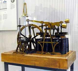
A reciprocating electric motor is a motor in which the armature moves back and forth rather than circularly. Early electric motors were sometimes of the reciprocating type, such as those made by Daniel Davis in the 1840s. Today, reciprocating electric motors are rare but they do have some niche applications, e.g. in linear compressors for cryogenics and as educational toys.

References

  1. Callihan, E E (1960), The magnetic field of a finite solenoid (PDF), NASA, retrieved 15 February 2024
  2. "How Does a Solenoid Work?".
  3. "Solenoid 101: What is a Solenoid?".
  4. Song, Chang-Wu (2015). "Design of a Solenoid Actuator with a Magnetic Plunger for Miniaturized Segment Robots". Applied Science. 5 (3): 595–607. Retrieved 17 April 2024.
  5. "Solenoid 101: What is a Solenoid?".
  6. "How to keep your doorbell ringing". Popular Science . No. March 1975. March 1975. p. 117. Archived from the original on 14 May 2018. Retrieved 29 November 2017.

Solenoid Force Calculations: https://www.keepandshare.com/doc18/25385/solenoidmagnetics-pdf-713k?da=y§