Amplitude modulation (AM) is a modulation technique used in electronic communication, most commonly for transmitting messages with a radio wave. In amplitude modulation, the amplitude of the wave is varied in proportion to that of the message signal, such as an audio signal. This technique contrasts with angle modulation, in which either the frequency of the carrier wave is varied, as in frequency modulation, or its phase, as in phase modulation.
Quadrature amplitude modulation (QAM) is the name of a family of digital modulation methods and a related family of analog modulation methods widely used in modern telecommunications to transmit information. It conveys two analog message signals, or two digital bit streams, by changing (modulating) the amplitudes of two carrier waves, using the amplitude-shift keying (ASK) digital modulation scheme or amplitude modulation (AM) analog modulation scheme. The two carrier waves are of the same frequency and are out of phase with each other by 90°, a condition known as orthogonality or quadrature. The transmitted signal is created by adding the two carrier waves together. At the receiver, the two waves can be coherently separated (demodulated) because of their orthogonality. Another key property is that the modulations are low-frequency/low-bandwidth waveforms compared to the carrier frequency, which is known as the narrowband assumption.

In electronics, an analog-to-digital converter is a system that converts an analog signal, such as a sound picked up by a microphone or light entering a digital camera, into a digital signal. An ADC may also provide an isolated measurement such as an electronic device that converts an analog input voltage or current to a digital number representing the magnitude of the voltage or current. Typically the digital output is a two's complement binary number that is proportional to the input, but there are other possibilities.
In signal processing, distortion is the alteration of the original shape of a signal. In communications and electronics it means the alteration of the waveform of an information-bearing signal, such as an audio signal representing sound or a video signal representing images, in an electronic device or communication channel.

In telecommunication, especially radio communication, spread spectrum are techniques by which a signal generated with a particular bandwidth is deliberately spread in the frequency domain over a wider frequency band. Spread-spectrum techniques are used for the establishment of secure communications, increasing resistance to natural interference, noise, and jamming, to prevent detection, to limit power flux density, and to enable multiple-access communications.
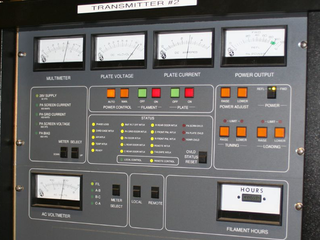
In electronics and telecommunications, a radio transmitter or just transmitter is an electronic device which produces radio waves with an antenna. The transmitter itself generates a radio frequency alternating current, which is applied to the antenna. When excited by this alternating current, the antenna radiates radio waves.
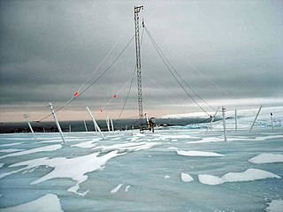
Very low frequency or VLF is the ITU designation for radio frequencies (RF) in the range of 3–30 kHz, corresponding to wavelengths from 100 to 10 km, respectively. The band is also known as the myriameter band or myriameter wave as the wavelengths range from one to ten myriameters. Due to its limited bandwidth, audio (voice) transmission is highly impractical in this band, and therefore only low data rate coded signals are used. The VLF band is used for a few radio navigation services, government time radio stations and for secure military communication. Since VLF waves can penetrate at least 40 meters (131 ft) into saltwater, they are used for military communication with submarines.

A power inverter, inverter, or invertor is a power electronic device or circuitry that changes direct current (DC) to alternating current (AC). The resulting AC frequency obtained depends on the particular device employed. Inverters do the opposite of rectifiers which were originally large electromechanical devices converting AC to DC.
A continuous wave or continuous waveform (CW) is an electromagnetic wave of constant amplitude and frequency, typically a sine wave, that for mathematical analysis is considered to be of infinite duration. It may refer to e.g. a laser or particle accelerator having a continuous output, as opposed to a pulsed output.

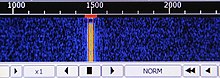
A spectrum analyzer measures the magnitude of an input signal versus frequency within the full frequency range of the instrument. The primary use is to measure the power of the spectrum of known and unknown signals. The input signal that most common spectrum analyzers measure is electrical; however, spectral compositions of other signals, such as acoustic pressure waves and optical light waves, can be considered through the use of an appropriate transducer. Spectrum analyzers for other types of signals also exist, such as optical spectrum analyzers which use direct optical techniques such as a monochromator to make measurements.

In mathematics, physics, electronics, control systems engineering, and statistics, the frequency domain refers to the analysis of mathematical functions or signals with respect to frequency, rather than time, as in time series. Put simply, a time-domain graph shows how a signal changes over time, whereas a frequency-domain graph shows how the signal is distributed within different frequency bands over a range of frequencies. A complex valued frequency-domain representation consists of both the magnitude and the phase of a set of sinusoids at the frequency components of the signal. Although it is common to refer to the magnitude portion as the frequency response of a signal, the phase portion is required to uniquely define the signal.
A variable frequency oscillator (VFO) in electronics is an oscillator whose frequency can be tuned over some range. It is a necessary component in any tunable radio transmitter and in receivers that works by the superheterodyne principle. The oscillator controls the frequency to which the apparatus is tuned.

A zero-crossing is a point where the sign of a mathematical function changes, represented by an intercept of the axis in the graph of the function. It is a commonly used term in electronics, mathematics, acoustics, and image processing.

A voltage-controlled oscillator (VCO) is an electronic oscillator whose oscillation frequency is controlled by a voltage input. The applied input voltage determines the instantaneous oscillation frequency. Consequently, a VCO can be used for frequency modulation (FM) or phase modulation (PM) by applying a modulating signal to the control input. A VCO is also an integral part of a phase-locked loop. VCOs are used in synthesizers to generate a waveform whose pitch can be adjusted by a voltage determined by a musical keyboard or other input.
Continuous phase modulation (CPM) is a method for modulation of data commonly used in wireless modems. In contrast to other coherent digital phase modulation techniques where the carrier phase abruptly resets to zero at the start of every symbol, with CPM the carrier phase is modulated in a continuous manner. For instance, with QPSK the carrier instantaneously jumps from a sine to a cosine whenever one of the two message bits of the current symbol differs from the two message bits of the previous symbol. This discontinuity requires a relatively large percentage of the power to occur outside of the intended band, leading to poor spectral efficiency. Furthermore, CPM is typically implemented as a constant-envelope waveform, i.e., the transmitted carrier power is constant. Therefore, CPM is attractive because the phase continuity yields high spectral efficiency, and the constant envelope yields excellent power efficiency. The primary drawback is the high implementation complexity required for an optimal receiver.

In electronics, noise is an unwanted disturbance in an electrical signal.
Acoustic quieting is the process of making machinery quieter by damping vibrations to prevent them from reaching the observer. Machinery vibrates, causing sound waves in air, hydroacoustic waves in water, and mechanical stresses in solid matter. Quieting is achieved by absorbing the vibrational energy or minimizing the source of the vibration. It may also be redirected away from the observer.
A bin-centres test signal is one which has been constructed such that it has frequency components at FFT bin-centre frequencies. This allows analysis without an FFT window function on a synchronous measurement system.
A superluminescent diode is an edge-emitting semiconductor light source based on superluminescence. It combines the high power and brightness of laser diodes with the low coherence of conventional light-emitting diodes. Its emission optical bandwidth, also described as full-width at half maximum, can range from 5 up to 750 nm.
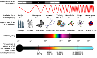
In the physical sciences, the term spectrum was introduced first into optics by Isaac Newton in the 17th century, referring to the range of colors observed when white light was dispersed through a prism. Soon the term referred to a plot of light intensity or power as a function of frequency or wavelength, also known as a spectral density plot.