Microwave is a form of electromagnetic radiation with wavelengths shorter than other radio waves but longer than infrared waves. Its wavelength ranges from about one meter to one millimeter, corresponding to frequencies between 300 MHz and 300 GHz, broadly construed. A more common definition in radio-frequency engineering is the range between 1 and 100 GHz, or between 1 and 3000 GHz . The prefix micro- in microwave is not meant to suggest a wavelength in the micrometer range; rather, it indicates that microwaves are small, compared to the radio waves used in prior radio technology.

In signal processing, a band-stop filter or band-rejection filter is a filter that passes most frequencies unaltered, but attenuates those in a specific range to very low levels. It is the opposite of a band-pass filter. A notch filter is a band-stop filter with a narrow stopband.
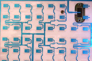
In telecommunication, a microstrip antenna usually is an antenna fabricated using photolithographic techniques on a printed circuit board (PCB). It is a kind of internal antenna. They are mostly used at microwave frequencies. An individual microstrip antenna consists of a patch of metal foil of various shapes on the surface of a PCB, with a metal foil ground plane on the other side of the board. Most microstrip antennas consist of multiple patches in a two-dimensional array. The antenna is usually connected to the transmitter or receiver through foil microstrip transmission lines. The radio frequency current is applied between the antenna and ground plane. Microstrip antennas have become very popular in recent decades due to their thin planar profile which can be incorporated into the surfaces of consumer products, aircraft and missiles; their ease of fabrication using printed circuit techniques; the ease of integrating the antenna on the same board with the rest of the circuit, and the possibility of adding active devices such as microwave integrated circuits to the antenna itself to make active antennas Patch antenna. Based on its origin, microstrip consists of two words, namely micro and is defined as a type of antenna that has a blade/piece shape and is very thin/small.

Microstrip is a type of electrical transmission line which can be fabricated with any technology where a conductor is separated from a ground plane by a dielectric layer known as "substrate". Microstrip lines are used to convey microwave-frequency signals.

A patch antenna is a type of antenna with a low profile, which can be mounted on a surface. It consists of a planar rectangular, circular, triangular, or any geometrical sheet or "patch" of metal, mounted over a larger sheet of metal called a ground plane. They are the original type of microstrip antenna described by Howell in 1972.
In microwave and radio-frequency engineering, a stub or resonant stub is a length of transmission line or waveguide that is connected at one end only. The free end of the stub is either left open-circuit, or short-circuited. Neglecting transmission line losses, the input impedance of the stub is purely reactive; either capacitive or inductive, depending on the electrical length of the stub, and on whether it is open or short circuit. Stubs may thus function as capacitors, inductors and resonant circuits at radio frequencies.
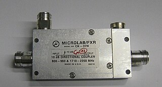
Power dividers and directional couplers are passive devices used mostly in the field of radio technology. They couple a defined amount of the electromagnetic power in a transmission line to a port enabling the signal to be used in another circuit. An essential feature of directional couplers is that they only couple power flowing in one direction. Power entering the output port is coupled to the isolated port but not to the coupled port. A directional coupler designed to split power equally between two ports is called a hybrid coupler.
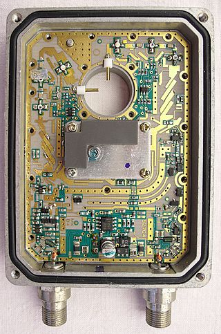
Radio frequency (RF) and microwave filters represent a class of electronic filter, designed to operate on signals in the megahertz to gigahertz frequency ranges. This frequency range is the range used by most broadcast radio, television, wireless communication, and thus most RF and microwave devices will include some kind of filtering on the signals transmitted or received. Such filters are commonly used as building blocks for duplexers and diplexers to combine or separate multiple frequency bands.
A distributed-element filter is an electronic filter in which capacitance, inductance, and resistance are not localised in discrete capacitors, inductors, and resistors as they are in conventional filters. Its purpose is to allow a range of signal frequencies to pass, but to block others. Conventional filters are constructed from inductors and capacitors, and the circuits so built are described by the lumped element model, which considers each element to be "lumped together" at one place. That model is conceptually simple, but it becomes increasingly unreliable as the frequency of the signal increases, or equivalently as the wavelength decreases. The distributed-element model applies at all frequencies, and is used in transmission-line theory; many distributed-element components are made of short lengths of transmission line. In the distributed view of circuits, the elements are distributed along the length of conductors and are inextricably mixed together. The filter design is usually concerned only with inductance and capacitance, but because of this mixing of elements they cannot be treated as separate "lumped" capacitors and inductors. There is no precise frequency above which distributed element filters must be used but they are especially associated with the microwave band.

Metamaterial antennas are a class of antennas which use metamaterials to increase performance of miniaturized antenna systems. Their purpose, as with any electromagnetic antenna, is to launch energy into free space. However, this class of antenna incorporates metamaterials, which are materials engineered with novel, often microscopic, structures to produce unusual physical properties. Antenna designs incorporating metamaterials can step-up the antenna's radiated power.

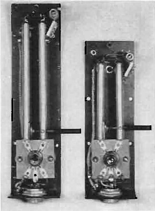
A waveguide filter is an electronic filter constructed with waveguide technology. Waveguides are hollow metal conduits inside which an electromagnetic wave may be transmitted. Filters are devices used to allow signals at some frequencies to pass, while others are rejected. Filters are a basic component of electronic engineering designs and have numerous applications. These include selection of signals and limitation of noise. Waveguide filters are most useful in the microwave band of frequencies, where they are a convenient size and have low loss. Examples of microwave filter use are found in satellite communications, telephone networks, and television broadcasting.
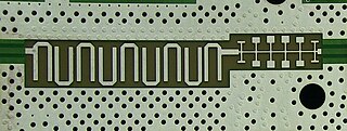
A via fence, also called a picket fence, is a structure used in planar electronic circuit technologies to improve isolation between components which would otherwise be coupled by electromagnetic fields. It consists of a row of via holes which, if spaced close enough together, form a barrier to electromagnetic wave propagation of slab modes in the substrate. Additionally if radiation in the air above the board is also to be suppressed, then a strip pad with via fence allows a shielding can to be electrically attached to the top side, but electrically behave as if it continued through the PCB.

Commensurate line circuits are electrical circuits composed of transmission lines that are all the same length; commonly one-eighth of a wavelength. Lumped element circuits can be directly converted to distributed-element circuits of this form by the use of Richards' transformation. This transformation has a particularly simple result; inductors are replaced with transmission lines terminated in short-circuits and capacitors are replaced with lines terminated in open-circuits. Commensurate line theory is particularly useful for designing distributed-element filters for use at microwave frequencies.

A waffle-iron filter is a type of waveguide filter used at microwave frequencies for signal filtering. It is a variation of the corrugated-waveguide filter but with longitudinal slots cut through the corrugations resulting in an internal structure that has the appearance of a waffle-iron.
Planar transmission lines are transmission lines with conductors, or in some cases dielectric (insulating) strips, that are flat, ribbon-shaped lines. They are used to interconnect components on printed circuits and integrated circuits working at microwave frequencies because the planar type fits in well with the manufacturing methods for these components. Transmission lines are more than simply interconnections. With simple interconnections, the propagation of the electromagnetic wave along the wire is fast enough to be considered instantaneous, and the voltages at each end of the wire can be considered identical. If the wire is longer than a large fraction of a wavelength, these assumptions are no longer true and transmission line theory must be used instead. With transmission lines, the geometry of the line is precisely controlled so that its electrical behaviour is highly predictable. At lower frequencies, these considerations are only necessary for the cables connecting different pieces of equipment, but at microwave frequencies the distance at which transmission line theory becomes necessary is measured in millimetres. Hence, transmission lines are needed within circuits.

A frequency-selective surface (FSS) is any thin, repetitive surface designed to reflect, transmit or absorb electromagnetic fields based on the frequency of the field. In this sense, an FSS is a type of optical filter or metal-mesh optical filters in which the filtering is accomplished by virtue of the regular, periodic pattern on the surface of the FSS. Though not explicitly mentioned in the name, FSS's also have properties which vary with incidence angle and polarization as well - these are unavoidable consequences of the way in which FSS's are constructed. Frequency-selective surfaces have been most commonly used in the radio frequency region of the electromagnetic spectrum and find use in applications as diverse as the aforementioned microwave oven, antenna radomes and modern metamaterials. Sometimes frequency selective surfaces are referred to simply as periodic surfaces and are a 2-dimensional analog of the new periodic volumes known as photonic crystals.

An inverted-F antenna is a type of antenna used in wireless communication, mainly at UHF and microwave frequencies. It consists of a monopole antenna running parallel to a ground plane and grounded at one end. The antenna is fed from an intermediate point a distance from the grounded end. The design has two advantages over a simple monopole: the antenna is shorter and more compact, allowing it to be contained within the case of the mobile device, and it can be impedance matched to the feed circuit by the designer, allowing it to radiate power efficiently, without the need for extraneous matching components.
Air stripline is a form of electrical planar transmission line whereby a conductor in the form of a thin metal strip is suspended between two ground planes. The idea is to make the dielectric essentially air. Mechanical support of the line may be a thin substrate, periodical insulated supports, or the device connectors and other electrical items.

Distributed-element circuits are electrical circuits composed of lengths of transmission lines or other distributed components. These circuits perform the same functions as conventional circuits composed of passive components, such as capacitors, inductors, and transformers. They are used mostly at microwave frequencies, where conventional components are difficult to implement.
A defected ground structure (DGS) is a purposefully created defect on the ground plane of a printed microstrip board. It is typically created in the form of an etched-out pattern on the ground plane. DGS is a simplified form of Electromagnetic Band Gap (EBG) structure. This EBG is a periodic pattern featuring a band-stop property in microstrip transmission line and circuit applications, but the DGS comprises a single defect or a very limited number of defects with periodic/aperiodic configurations.