
A biplane is a fixed-wing aircraft with two main wings stacked one above the other. The first powered, controlled aeroplane to fly, the Wright Flyer, used a biplane wing arrangement, as did many aircraft in the early years of aviation. While a biplane wing structure has a structural advantage over a monoplane, it produces more drag than a monoplane wing. Improved structural techniques, better materials and higher speeds made the biplane configuration obsolete for most purposes by the late 1930s.

A tailplane, also known as a horizontal stabiliser, is a small lifting surface located on the tail (empennage) behind the main lifting surfaces of a fixed-wing aircraft as well as other non-fixed-wing aircraft such as helicopters and gyroplanes. Not all fixed-wing aircraft have tailplanes. Canards, tailless and flying wing aircraft have no separate tailplane, while in V-tail aircraft the vertical stabiliser, rudder, and the tail-plane and elevator are combined to form two diagonal surfaces in a V layout.

In fluid dynamics, angle of attack is the angle between a reference line on a body and the vector representing the relative motion between the body and the fluid through which it is moving. Angle of attack is the angle between the body's reference line and the oncoming flow. This article focuses on the most common application, the angle of attack of a wing or airfoil moving through air.
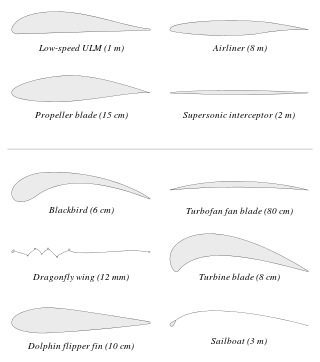
An airfoil or aerofoil is the cross-sectional shape of an object whose motion through a gas is capable of generating significant lift, such as a wing, a sail, or the blades of propeller, rotor, or turbine.

In aeronautics, dihedral is the angle between the left and right wings of an aircraft. "Dihedral" is also used to describe the effect of sideslip on the rolling of the aircraft.

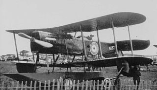
The Sopwith Triplane was a British single seat fighter aircraft designed and manufactured by the Sopwith Aviation Company during the First World War. It has the distinction of being the first military triplane to see operational service.

A triplane is a fixed-wing aircraft equipped with three vertically stacked wing planes. Tailplanes and canard foreplanes are not normally included in this count, although they occasionally are.
A flap is a high-lift device used to reduce the stalling speed of an aircraft wing at a given weight. Flaps are usually mounted on the wing trailing edges of a fixed-wing aircraft. Flaps are used to reduce the take-off distance and the landing distance. Flaps also cause an increase in drag so they are retracted when not needed.

The Gurney flap is a small tab projecting from the trailing edge of a wing. Typically it is set at a right angle to the pressure-side surface of the airfoil and projects 1% to 2% of the wing chord. This trailing edge device can improve the performance of a simple airfoil to nearly the same level as a complex high-performance design.
In aeronautics and aeronautical engineering, camber is the asymmetry between the two acting surfaces of an airfoil, with the top surface of a wing commonly being more convex. An airfoil that is not cambered is called a symmetric airfoil. The benefits of cambering were discovered and first utilized by George Cayley in the early 19th century.

Decalage on a fixed-wing aircraft is the angle difference between the upper and lower wings of a biplane, i.e. the acute angle contained between the chords of the wings in question.

The Parker variable wing is a wing configuration in biplane or triplane aircraft designed by H.F. Parker in 1920. His design allows a supplement in lift while landing or taking-off. The system is depicted in the figure. The figure shows the biplane configuration. The lower airfoil is rigid. The upper airfoil is flexible. At high angle of attack the flow over the lower airfoil will cause the airflow to bend up and create an upward force at the lower surface of the upper airfoil. This upward force will cause the flexible section to be pushed upward. The flexible wing section is held at points A and B. The trailing edge is rigid and can rotate about point B. Due to this effect the camber of the airfoil is increased, and hence the lift it creates is increased.
Deflected slipstream is an approach to creating an aircraft that can take off and land vertically (VTOL), or at least with a very short runway (STOL). The basic principle is to deflect the slipstream from one or more propellers approximately 90 degrees, to create an upward thrust for vertical takeoff and a downward air cushion for landing. Once airborne, the flaps are retracted so the airplane can fly horizontally.

The wing configuration of a fixed-wing aircraft is its arrangement of lifting and related surfaces.

The Gloster TC.33 was a large four-engined biplane designed for troop carrying and medical evacuation in the early 1930s. Only one was built.
The Sopwith Snark was a British prototype fighter aircraft designed and built towards the end of the First World War to replace the RAF's Sopwith Snipes. A single engined triplane, the Snark did not fly until after the end of the war, only three being built.
The Parnall Puffin was an experimental amphibious fighter-reconnaissance biplane produced in the United Kingdom just after World War I. It had several unusual features, principally a single central float and an inverted vertical stabilizer and rudder, and showed promise, but at that time no new aircraft were being ordered in numbers for the RAF and only the three Puffins of the initial order were built.
In aviation, a multiplane is a fixed-wing aircraft-configuration featuring multiple wing planes. The wing planes may be stacked one above another, or one behind another, or both in combination. Types having a small number of planes have specific names and are not usually described as multiplanes:
The Starck AS-27 Starcky was a racing single seat biplane of unusual wing layout with full stagger and a small gap. It was designed and built in France in the 1970s; only one was made.
In aeronautics, bracing comprises additional structural members which stiffen the functional airframe to give it rigidity and strength under load. Bracing may be applied both internally and externally, and may take the form of struts, which act in compression or tension as the need arises, and/or wires, which act only in tension.

