The decibel is a relative unit of measurement equal to one tenth of a bel (B). It expresses the ratio of two values of a power or root-power quantity on a logarithmic scale. Two signals whose levels differ by one decibel have a power ratio of 101/10 or root-power ratio of 101⁄20.
In telecommunications, orthogonal frequency-division multiplexing (OFDM) is a type of digital transmission used in digital modulation for encoding digital (binary) data on multiple carrier frequencies. OFDM has developed into a popular scheme for wideband digital communication, used in applications such as digital television and audio broadcasting, DSL internet access, wireless networks, power line networks, and 4G/5G mobile communications.
In telecommunications and professional audio, a balanced line or balanced signal pair is a circuit consisting of two conductors of the same type, both of which have equal impedances along their lengths and equal impedances to ground and to other circuits. The primary advantage of the balanced line format is good rejection of common-mode noise and interference when fed to a differential device such as a transformer or differential amplifier.
Noise figure (NF) and noise factor (F) are figures of merit that indicate degradation of the signal-to-noise ratio (SNR) that is caused by components in a signal chain. These figures of merit are used to evaluate the performance of an amplifier or a radio receiver, with lower values indicating better performance.
In electronics, noise temperature is one way of expressing the level of available noise power introduced by a component or source. The power spectral density of the noise is expressed in terms of the temperature that would produce that level of Johnson–Nyquist noise, thus:
In telecommunications, a third-order intercept point (IP3 or TOI) is a specific figure of merit associated with the more general third-order intermodulation distortion (IMD3), which is a measure for weakly nonlinear systems and devices, for example receivers, linear amplifiers and mixers. It is based on the idea that the device nonlinearity can be modeled using a low-order polynomial, derived by means of Taylor series expansion. The third-order intercept point relates nonlinear products caused by the third-order nonlinear term to the linearly amplified signal, in contrast to the second-order intercept point that uses second-order terms.

Coaxial cable, or coax is a type of electrical cable consisting of an inner conductor surrounded by a concentric conducting shield, with the two separated by a dielectric ; many coaxial cables also have a protective outer sheath or jacket. The term coaxial refers to the inner conductor and the outer shield sharing a geometric axis.
A low-noise block downconverter (LNB) is the receiving device mounted on satellite dishes used for satellite TV reception, which collects the radio waves from the dish and converts them to a signal which is sent through a cable to the receiver inside the building. Also called a low-noise block, low-noise converter (LNC), or even low-noise downconverter (LND), the device is sometimes inaccurately called a low-noise amplifier (LNA).
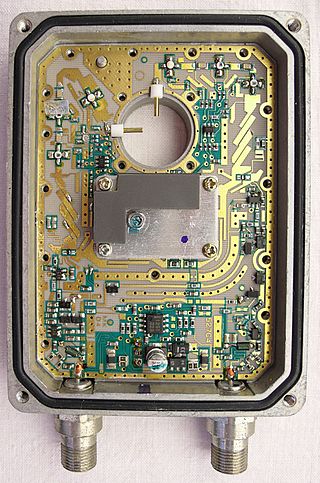
A low-noise amplifier (LNA) is an electronic amplifier that amplifies a very low-power signal without significantly degrading its signal-to-noise ratio. An amplifier will increase the power of both the signal and the noise present at its input, but the amplifier will also introduce some additional noise. LNAs are designed to minimize that additional noise. Designers can minimize additional noise by choosing low-noise components, operating points, and circuit topologies. Minimizing additional noise must balance with other design goals such as power gain and impedance matching.
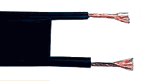
Twin-lead cable is a two-conductor flat cable used as a balanced transmission line to carry radio frequency (RF) signals. It is constructed of two stranded or solid copper or copper-clad steel wires, held a precise distance apart by a plastic ribbon. The uniform spacing of the wires is the key to the cable's function as a transmission line; any abrupt changes in spacing would reflect some of the signal back toward the source. The plastic also covers and insulates the wires. It is available with several different values of characteristic impedance, the most common type is 300 ohm.

A preamplifier, also known as a preamp, is an electronic amplifier that converts a weak electrical signal into an output signal strong enough to be noise-tolerant and strong enough for further processing, or for sending to a power amplifier and a loudspeaker. Without this, the final signal would be noisy or distorted. They are typically used to amplify signals from analog sensors such as microphones and pickups. Because of this, the preamplifier is often placed close to the sensor to reduce the effects of noise and interference.
The sensitivity of an electronic device, such as a communications system receiver, or detection device, such as a PIN diode, is the minimum magnitude of input signal required to produce a specified output signal having a specified signal-to-noise ratio, or other specified criteria.

An antenna tuner is an electronic device in the feedline between a radio transmitter and its antenna. Its purpose is to optimize power transfer by matching the impedance of the radio to the impedance of the end of the feedline connecting the antenna to the transmitter.

Direction finding (DF), or radio direction finding (RDF), is – in accordance with International Telecommunication Union (ITU) – defined as radio location that uses the reception of radio waves to determine the direction in which a radio station or an object is located. This can refer to radio or other forms of wireless communication, including radar signals detection and monitoring (ELINT/ESM). By combining the direction information from two or more suitably spaced receivers, the source of a transmission may be located via triangulation. Radio direction finding is used in the navigation of ships and aircraft, to locate emergency transmitters for search and rescue, for tracking wildlife, and to locate illegal or interfering transmitters. RDF was important in combating German threats during both the World War II Battle of Britain and the long running Battle of the Atlantic. In the former, the Air Ministry also used RDF to locate its own fighter groups and vector them to detected German raids.
Friis formula or Friis's formula, named after Danish-American electrical engineer Harald T. Friis, is either of two formulas used in telecommunications engineering to calculate the signal-to-noise ratio of a multistage amplifier. One relates to noise factor while the other relates to noise temperature.

A parametric oscillator is a driven harmonic oscillator in which the oscillations are driven by varying some parameter of the system at some frequency, typically different from the natural frequency of the oscillator. A simple example of a parametric oscillator is a child pumping a playground swing by periodically standing and squatting to increase the size of the swing's oscillations. The child's motions vary the moment of inertia of the swing as a pendulum. The "pump" motions of the child must be at twice the frequency of the swing's oscillations. Examples of parameters that may be varied are the oscillator's resonance frequency and damping .
In the field of wireless communication, macrodiversity is a kind of space diversity scheme using several receiver or transmitter antennas for transferring the same signal. The distance between the transmitters is much longer than the wavelength, as opposed to microdiversity where the distance is in the order of or shorter than the wavelength.

In radio, multiple-input and multiple-output, or MIMO, is a method for multiplying the capacity of a radio link using multiple transmission and receiving antennas to exploit multipath propagation. MIMO has become an essential element of wireless communication standards including IEEE 802.11n, IEEE 802.11ac, HSPA+ (3G), WiMAX, and Long Term Evolution (LTE). More recently, MIMO has been applied to power-line communication for three-wire installations as part of the ITU G.hn standard and of the HomePlug AV2 specification.
Differential gain is a kind of linearity distortion which affects the color saturation in TV broadcasting.
An RF chain is a cascade of electronic components and sub-units which may include amplifiers, filters, mixers, attenuators and detectors. It can take many forms, for example, as a wide-band receiver-detector for electronic warfare (EW) applications, as a tunable narrow-band receiver for communications purposes, as a repeater in signal distribution systems, or as an amplifier and up-converters for a transmitter-driver. In this article, the term RF covers the frequency range "Medium Frequencies" up to "Microwave Frequencies", i.e. from 100 kHz to 20 GHz.


