Vibratory Stress Relief, often abbreviated VSR, is a non-thermal stress relief method used by the metal working industry to enhance the dimensional stability and mechanical integrity of castings, forgings, and welded components, chiefly for two categories of these metal workpieces:
Heavily loaded metal workpieces, which are components designed and built with the ability to withstand heavy loads. Examples include lifting yokes, clamshell buckets, crane bases, vibratory screening system frames, ingot processing equipment, and rolling mill equipment.
This stress is called residual stress,[1] because it remains in a solid material after the original cause of the stress has been removed. Residual stresses can occur through a variety of mechanisms including inelastic (plastic) deformations, temperature gradients (during thermal cycle), or structural changes (phase transformation). For example, heat from welding may cause localized expansion, which is taken up during welding by either the molten metal or the placement of parts being welded. When the finished weldment cools, some areas cool and contract more than others, leaving residual stresses. These stresses often lead to distortion or warping of the structure during machining, assembly, testing, transport, field-use or over time. In extreme cases, residual stress can cause structural failure.
Almost all vibratory stress relief equipment manufacturers and procedures use the workpiece's own resonant frequency to boost the loading experienced by induced vibration, so to maximize the degree of stress relief achieved. Some equipment and procedures are designed to operate near, but not at, workpiece resonances (perhaps to extend equipment life). Although, independent research [2] has consistently shown resonant frequency vibration to be more effective. See references 4, 6, and 9.
The effectiveness of vibratory stress relief is highly questionable.[3] In general, the strain amplitudes achieved during vibratory stress relief are too low to exceed the critical stress required to activate mechanical relaxation during the induced low amplitude high cycle fatigue excitation of the transducer vibrations. If the strain amplitudes were increased to a level sufficient to cause instability in the residual stresses, fatigue damage would occur.[4][5] For most applications, conventional stress relief methodologies should be applied to components that require the reduction of residual stresses.[6]
Criteria for effective VSR treatment
Effective vibratory stress relief treatment results from a combination of factors:
1. Material condition: The material must be ductile. Metal in the welded, cast, forged, or hot-rolled condition can be treated. Material that has been severely cold-rolled or through-hardened, which renders the metal non-ductile, will resist effective treatment.
2. Component geometry: Large workpieces lend themselves well to vibratory stress relief, likely due to their being more able to be resonated, however a variety of modest-sized workpieces (overall size less than 20" / 500 mm) have been effectively stress relieved, using vibration.
3. Setup for VSR Treatment involves several steps.
Placing workpiece upon load cushions. These cushions should be made of soft, yet resilient material, typically urethane or neoprene. The cushions should be placed away from the corners of the workpiece, so that workpiece damping is minimized, which promotes increased resonant response to vibration.
Positioning, orienting, and securely clamping vibrator on workpiece. The vibrator should be placed away from the corners of the workpiece, and oriented so that the force-field output of the vibrator, with rotary vibrators a plane perpendicular to the vibrator’s axis of rotation, can drive the workpiece into resonance. Dual-mount-flanged vibrators are helpful in achieving effective orientation. The vibrator must be securely clamped, typically with machinist-grade clamps or high-tensile bolts.
Positioning and orienting vibration sensor. The best location for this sensor is on one of the corners of the workpiece, and in-line with the force-plane of the vibrator (a plane perpendicular to the vibrator’s axis of rotation [AOR]).
Adjustment of the vibrator unbalance. The unbalance of the vibrator should be sufficient to drive the resonances of the workpiece, minimally to a level of a few g’s of acceleration. The unbalance might require further increase, to cause peak growth (discussed later) during stress relief treatment.
4. Finding Resonance(s). The vibrator speed range must reach high enough to be greater than the resonance(s) of the workpiece. A max speed capability of at least 6000 – 8000-RPM is recommended. Equally important is tight vibrator motor speed regulation (±0.25%), which greatly improves the ability to detect and drive the resonance(s) (abilities that are required for stress relieving to occur). Driving a resonance involves tuning the vibrator speed to the top of the resonance peak. This is increasingly challenging as workpiece rigidity increases, which causes resonances to become very narrow. To record such resonances, a slow, automated scan through the speed range and plotting of the vibration response of the workpiece is made.
The scan rate must be slow, not only because the resonance peaks are narrow, but also due to the high-inertia of the workpiece. There is a significant time delay, caused by this high workpiece inertia, in the response to vibration. This can be best explained by first looking at the phenomenon known as ring time.
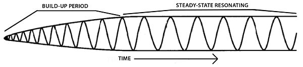
Ring time is defined as the time period a resonating body continues to vibrate after resonant excitation is stopped. When the vibration is stopped, the waveform will decay, ie, reduce in amplitude, due to frictional losses. See Figure 1
Figure 1: A waveform that demonstrates ring time, which is the time period vibration continues, after resonant excitation ceases.
Most people have experienced ring time. A large bell, after being struck, continues to emit sound, but at decreasing (softer) sound levels. Over time, the sound level dissipates, as the vibration amplitude decays to an undetectable level.
When vibration is the excitation causing resonance (rather than a hammer blow [such as the strike of a bell]), there is a time period between the beginning of vibration excitation, and the moment when full resonant amplitude is reached. During this time the amplitude is building-up or growing (the reverse of decaying), so this phenomenon is called reverse ring time, or RRT. For large metal structures that are commonly stress relieved with vibration, ring or reverse ring times (the time periods are the same, whether the amplitude is growing or decaying), can be 20 – 40 seconds or longer. See Figure 2.
Figure 2: Reverse ring time, or RRT, is the time period between the start of vibration excitation, and full resonant amplitude.
The most frequently used method of finding the resonances of a workpiece during vibratory stress relief is to scan through the vibrator speed range, and record / plot the vibration amplitude vs. the vibrator speed. The effect of RRT, specifically the time delay between the beginning of resonant vibration and full resonant amplitude being achieved, dictates that the scan rate used to sweep through the vibrator speed range be slow, in order to make an accurate record of the resonance pattern.
Scanning too quickly will result in resonant peaks not being fully depicted or being missed entirely, since the workpiece will not have sufficient time to reach full amplitude resonance before the vibrator speed increases (due to scanning) beyond the resonance frequency.
A scan rate of 10-RPM / second has been found in practice to result in the accurate resonant peaks recording of many workpieces. As workpiece size increases, the scan rate might require being decreased, in order to fully capture accurate resonance data. See Figure 3.
Figure 3: The effects of scanning at different scan rates: 10 and 50-RPM/sec. Peaks that are scanned too quickly don't have enough time to reach full resonant amplitude, due to the RRT effect. The larger and heavier the structure, the greater the inertia, the longer the ring time (and reverse ring time): Thus, larger, heavier structures might require slower scan rates to plot accurate resonance patterns.
5. Tuning Vibrator Speed. The vibrator speed is then tuned upon the resonance(s) recorded during the scan, and the response of the workpiece to vibration is monitored. Fine tuning of the speed, plus tight speed regulation, enhances peak tuning and tracking capabilities. The most common responses to treatment are:
Peak Growth - Typically the larger change.
Peak Shift, in the direction of lower RPM - Percentage-wise, the smaller change. Typically resonance peaks are very narrow, causing any peak shifting to rapidly decrease the vibration amplitude, and hence, rapidly decrease of the rate of stress relief, since resonant amplitude is more effective in relieving stress. Thus, any peak shifting requires fine-tuning adjustment of the vibrator speed, in order to track the peak to its final, stable position.
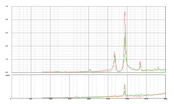
Each of these changes, which often combine, i.e., peak growth AND shifting, is consistent with a lowering of the rigidity of the workpiece. The workpiece rigidity is inflated by the presence of residual stress. In the example below, which depicts a common resonance pattern change that occurs during vibratory stress relief, the large peak grew by 47%, while simultaneously shifting to the left 28-RPM, which is less than 0.75%. See Figure 4.
The equipment used to perform this stress relief had vibrator speed regulation of ± 0.02%, and speed increment fine-tuning of 1-RPM, which allowed even subtle shifting of the peaks to be accurately tracked to their final, stable locale.
The pattern of change, i.e., how quickly the peaks grow and shift, is faster at the beginning of vibration treatment: As treatment continues, the rate of change decreases, eventually resulting in a new, stable resonance pattern. Stability of this new resonance pattern indicates that dimensional stability of the workpiece has been achieved.
Figure 4: VSR Treatment Chart consists of two plots: The upper plot is workpiece acceleration, the lower plot is vibrator input power, simultaneously plotted vertically vs. a common horizontal axis of vibrator speed. Peaks in the acceleration data depict resonances; growth and shifting of the peaks are the response of the workpiece to treatment.
The power plot is useful in both positioning and orienting the vibrator, and when adjusting the vibrator unbalance. Poor or inappropriate vibrator locations or orientations, or excessive vibrator unbalance settings, cause large peaks in the power plot. Use of higher-powered vibrator motors (above 2-kW) provides more "head-room" for peaks in power to be tolerated, and treatment to take place, which was the case here: The power peak at ≈ 3700-RPM was only half of the vibrator motor's 2.3-kW power capacity (top of the power scale).
A Pre-Treatment Scan, which functions as a base-line, is first recorded in green. The operator uses this green data set to tune upon the resonances, and monitor the growth and shifting of the resonance peaks. After peak growth and shifting have subsided, a Post-Treatment Scan is made (red). This data is superimposed on the original, green, Pre-Treatment Scan data, documenting the changes in resonance pattern. The stress relief treatment resulted in 47% growth of the original, large peak, while it shifted to the left 28-RPM (less than 0.75%).
Figure 5: Vibratory Stress Relief was performed on this mild steel weldment weighing almost 12 tons. Overall size was 17' × 15' × 2' (≈ 5.2 × 5.6 × 0.6 meters). Workpiece was supported on three, red urethane load cushions (two of which are circled), which are positioned far from the corners of the workpiece to minimize damping, thus promoting resonance, which is required for stress relief to be achieved. The vibrator can be seen in the left, mid-ground (circled), and the accelerometer (vibration sensor whose output is proportional to acceleration), can be seen in the central, left, foreground (circled).
After stress relief treatment, the braces (rust-colored, structural beams), which are used to maintain the desired shape during welding, were removed. The spacing between the two "arms" remained the same; no change was detectable (measured to 1/32" or less than 1mm), and the spacing remained so throughout assembly, testing (to 60 ton test loads), transport, and installation.
When should VSR be considered and the limits of TSR
VSR is not accepted by the Engineering community at large as a viable method of relaxing or reducing residual stresses in components that require it. For general use, conventional residual stress relaxation methodologies are recommended.[9]
Historically, the first type of stress relief was performed on castings by storing them outside for months or even years. This was referred to as curing, a term used for long-term storage of freshly hewn wood. Fresh castings were referred to as being green, meaning, they were prone to distortion during precision machining, just as green wood bows during cutting.
Later, thermal stress relief (TSR) was developed to alleviate the lengthy time requirements of curing. It has been known for many years, however, that TSR has limitations or shortcomings, specifically:
Should not be used on welded structures made of low-carbon, high-strength steels, which can suffer loss of physical properties and/or crack initiation if thermally stress relieved.[10][11]
Cannot be used on workpieces that have been quenched and tempered (Q&T) without risking loss of physical properties. Vibratory stress relief can be successfully applied, if some level of ductility is present after Q&T, together with acceptable workpiece geometry (which determines resonant vibration frequency required).
Often not suitable for rough-machined components, due to difficulty in removing scale (rust-colored skin that develops on ferrous components while in-furnace), without damaging machined surfaces.
Asymmetrical-shaped workpieces, which are difficult to cool while maintaining uniform temperature, can develop new, unacceptably high-level, residual stress patterns during the last stage of TSR. Cooling rates can be slowed, but with increased costs.
Metal components, whose function would be enhanced by stress relief, and fall into one or more of the above categories, are strong candidates for VSR for quality-related reasons.
Further, there is a strong economic incentive to use vibratory stress relief on large workpieces, since stress relief using a furnace (thermal stress relief or TSR) is highly energy-intensive; consuming much natural gas, and hence, producing much CO2. The cost of TSR is approximately proportional to a metal component's weight or overall size, estimated to be US$2,500 for the structure pictured, plus transportation costs, which might involve special transport permits, to and from a furnace. VSR Treatment would cost a company owning appropriate equipment less than 15% as much ( ≈ $400 ) as TSR Treatment, chiefly amortization of equipment investment plus labor, and a modest amount of electrical consumption, and treatment would take less than two hours, with no transport required. However, the lack of independent data to show that this technique is effective may mean that even that lesser investment is not of any value, so use of VSR should evaluated very carefully before proceeding.
Related Research Articles
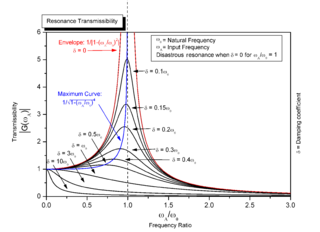
Resonance is the phenomenon, pertaining to oscillatory dynamical systems, wherein amplitude rises are caused by an external force with time-varying amplitude with the same frequency of variation as the natural frequency of the system. The amplitude rises occur in resonance owing to the fact that applied external forces at the natural frequency entail a net increase in mechanical energy of the system.
Shielded metal arc welding (SMAW), also known as manual metal arc welding, flux shielded arc welding or informally as stick welding, is a manual arc welding process that uses a consumable electrode covered with a flux to lay the weld.
Nondestructive testing (NDT) is any of a wide group of analysis techniques used in science and technology industry to evaluate the properties of a material, component or system without causing damage. The terms nondestructive examination (NDE), nondestructive inspection (NDI), and nondestructive evaluation (NDE) are also commonly used to describe this technology. Because NDT does not permanently alter the article being inspected, it is a highly valuable technique that can save both money and time in product evaluation, troubleshooting, and research. The six most frequently used NDT methods are eddy-current, magnetic-particle, liquid penetrant, radiographic, ultrasonic, and visual testing. NDT is commonly used in forensic engineering, mechanical engineering, petroleum engineering, electrical engineering, civil engineering, systems engineering, aeronautical engineering, medicine, and art. Innovations in the field of nondestructive testing have had a profound impact on medical imaging, including on echocardiography, medical ultrasonography, and digital radiography.
Metalworking is the process of shaping and reshaping metals to create useful objects, parts, assemblies, and large scale structures. As a term it covers a wide and diverse range of processes, skills, and tools for producing objects on every scale: from huge ships, buildings, and bridges down to precise engine parts and delicate jewelry.
A drill string on a drilling rig is a column, or string, of drill pipe that transmits drilling fluid and torque to the drill bit. The term is loosely applied to the assembled collection of the smuggler pool, drill collars, tools and drill bit. The drill string is hollow so that drilling fluid can be pumped down through it and circulated back up the annulus.
Induction heating is the process of heating electrically conductive materials, namely metals or semi-conductors, by electromagnetic induction, through heat transfer passing through an inductor that creates an electromagnetic field within the coil to heat up and possibly melt steel, copper, brass, graphite, gold, silver, aluminum, or carbide.
Ultrasonic welding is an industrial process whereby high-frequency ultrasonic acoustic vibrations are locally applied to work pieces being held together under pressure to create a solid-state weld. It is commonly used for plastics and metals, and especially for joining dissimilar materials. In ultrasonic welding, there are no connective bolts, nails, soldering materials, or adhesives necessary to bind the materials together. When used to join metals, the temperature stays well below the melting point of the involved materials, preventing any unwanted properties which may arise from high temperature exposure of the metal.
Drilling is a cutting process where a drill bit is spun to cut a hole of circular cross-section in solid materials. The drill bit is usually a rotary cutting tool, often multi-point. The bit is pressed against the work-piece and rotated at rates from hundreds to thousands of revolutions per minute. This forces the cutting edge against the work-piece, cutting off chips (swarf) from the hole as it is drilled.
Carburizing, or carburising, is a heat treatment process in which iron or steel absorbs carbon while the metal is heated in the presence of a carbon-bearing material, such as charcoal or carbon monoxide. The intent is to make the metal harder and more wear resistant. Depending on the amount of time and temperature, the affected area can vary in carbon content. Longer carburizing times and higher temperatures typically increase the depth of carbon diffusion. When the iron or steel is cooled rapidly by quenching, the higher carbon content on the outer surface becomes hard due to the transformation from austenite to martensite, while the core remains soft and tough as a ferritic and/or pearlite microstructure.
Shot peening is a cold working process used to produce a compressive residual stress layer and modify the mechanical properties of metals and composites. It entails striking a surface with shot with force sufficient to create plastic deformation.
In materials science and solid mechanics, residual stresses are stresses that remain in a solid material after the original cause of the stresses has been removed. Residual stress may be desirable or undesirable. For example, laser peening imparts deep beneficial compressive residual stresses into metal components such as turbine engine fan blades, and it is used in toughened glass to allow for large, thin, crack- and scratch-resistant glass displays on smartphones. However, unintended residual stress in a designed structure may cause it to fail prematurely.
Mechanical resonance is the tendency of a mechanical system to respond at greater amplitude when the frequency of its oscillations matches the system's natural frequency of vibration closer than it does other frequencies. It may cause violent swaying motions and potentially catastrophic failure in improperly constructed structures including bridges, buildings and airplanes. This is a phenomenon known as resonance disaster.
A photoelastic modulator (PEM) is an optical device used to modulate the polarization of a light source. The photoelastic effect is used to change the birefringence of the optical element in the photoelastic modulator.
A vibrator is a mechanical device to generate vibrations. The vibration is often generated by an electric motor with an unbalanced mass on its driveshaft.
In ultrasonic machining, welding and mixing, a sonotrode is a tool that creates ultrasonic vibrations and applies this vibrational energy to a gas, liquid, solid or tissue.
Mechanical plating, also known as peen plating, mechanical deposition, or impact plating, is a plating process that imparts the coating by cold welding fine metal particles to a workpiece. Mechanical galvanization is the same process, but applies to coatings that are thicker than 0.001 in (0.025 mm). It is commonly used to overcome hydrogen embrittlement problems. Commonly plated workpieces include nails, screws, nuts, washers, stampings, springs, clips, and sintered iron components.
Ultrasonic impact treatment (UIT) is a metallurgical processing technique, similar to work hardening, in which ultrasonic energy is applied to a metal object. This technique is part of the High Frequency Mechanical Impact (HFMI) processes. Other acronyms are also equivalent: Ultrasonic Needle Peening (UNP), Ultrasonic Peening (UP). Ultrasonic impact treatment can result in controlled residual compressive stress, grain refinement and grain size reduction. Low and high cycle fatigue are enhanced and have been documented to provide increases up to ten times greater than non-UIT specimens.
Rotating unbalance is the uneven distribution of mass around an axis of rotation. A rotating mass, or rotor, is said to be out of balance when its center of mass is out of alignment with the center of rotation. Unbalance causes a moment which gives the rotor a wobbling movement characteristic of vibration of rotating structures.
Tumbler screening is a separation method that uses three-dimensional elliptical movement to separate very fine particles from larger ones.
Vibration welding refers to a process in which two workpieces are brought in contact under pressure, and a reciprocating motion (vibration) is applied along the common interface in order to generate heat. The resulting heat melts the workpieces, and they become welded when the vibration stops and the interface cools. Most machinery operates at 120 Hz, although equipment is available that runs between 100–240 Hz. Vibration can be achieved either through linear vibration welding, which uses a one dimensional back and forth motion, or orbital vibration welding which moves the pieces in small orbits relative to each other. Linear vibration welding is more common due to simpler and relatively cheaper machinery required.
References
Notes
↑ R.T. McGoldrick and H. Saunders, Some Experiments in Stress-Relieving Castings and Structures by Vibration, Journal of the American Society of Naval Engineer., 55, 589-609 (1943)
↑ R. Dawson and D.G. Moffat, Vibratory Stress Relief: A Fundamental Study of Effectiveness, Journal of Engineering Material and Technology, 102, 169-176 (1980)
↑ J. Stubbs, "Vibratory/Thermal Stress Relief in a Weld Joint", Case Western Reserve University, 2003.
↑ G. Totten et al. "ASM Handbook of Residual Stress and Deformation in Steel", 2001 p.54-67
↑ R. Dawson and D.G. Moffat, Vibratory Stress Relief: A Fundamental Study of Effectiveness, Journal of Engineering Material and Technology, 102, 169-176 (1980)
↑ C.A. Walker, A.J. Waddell and D.J. Johnston, Vibratory Stress Relief - An Investigation of the Underlying Process, Proc. Inst. Mechanical Engineers., 209, 51-58 (1995)
↑ S. Shakar, Vibratory Stress Relief of Mild Steel Weldments, PhD Dissertation, Oregon Graduate Center, U. of Oregon, 1982
↑ B.B. Klauba and C.M. Adams, A Progress Report on the Use and Understanding of Vibratory Stress Relief, Proc. Winter Meeting of the ASME AMD 52, 47-57 (1982)
↑ W. Hahn, Report on Vibratory Stress and Modifications in Materials to Conserve Resources and Prevent Pollution, Alfred University (NY), Center for Environmental and Energy Research (CEER), 2002
Bibliography
PDF D. Rao, J. Ge, and L. Chen, Vibratory Stress Relief in the Manufacturing the Rails of a Maglev System, J. of Manufacturing Science and Engineering, 126, Issue 2, 388-391 (2004)
PDF B.B. Klauba, C.M. Adams, J.T. Berry, Vibratory Stress Relief: Methods Used to Monitor and Document Effective Treatment, A Survey of Users, and Directions for Further Research, Proc. of ASM, 7th International Conference: Trends in Welding Research 601-606 (2005)
PDF Y. Yang, G. Jung, and R. Yancey, Finite Element Modeling of Vibratory Stress Relief after Welding, Proc of ASM, 7th International Conference; Trends in Welding Research 547-552 (2005)
This page is based on this Wikipedia article Text is available under the CC BY-SA 4.0 license; additional terms may apply. Images, videos and audio are available under their respective licenses.


![Figure 5: Vibratory Stress Relief was performed on this mild steel weldment weighing almost 12 tons. Overall size was 17' x 15' x 2' ([?] 5.2 x 5.6 x 0.6 meters). Workpiece was supported on three, red urethane load cushions (two of which are circled), which are positioned far from the corners of the workpiece to minimize damping, thus promoting resonance, which is required for stress relief to be achieved. The vibrator can be seen in the left, mid-ground (circled), and the accelerometer (vibration sensor whose output is proportional to acceleration), can be seen in the central, left, foreground (circled). SteelWeldments.jpg](http://upload.wikimedia.org/wikipedia/commons/thumb/4/46/SteelWeldments.jpg/600px-SteelWeldments.jpg)