A voltage-controlled resistor (VCR) is a three-terminal active device with one input port and two output ports. The input-port voltage controls the value of the resistor between the output ports. VCRs are most often built with field-effect transistors (FETs). Two types of FETs are often used: the JFET and the MOSFET. There are both floating voltage-controlled resistors and grounded voltage-controlled resistors. Floating VCRs can be placed between two passive or active components. Grounded VCRs, the more common and less complicated design, require that one port of the voltage-controlled resistor be grounded.
The JFET is one of the more common active devices used for the design of voltage-controlled resistors. So much so, that JFET devices are packaged and sold as voltage-controlled resistors.[21] Typically, JFETs when they are packaged as VCRs often have high pinch-off voltages, which result in a greater dynamic resistance range. JFETs for VCRs are often packaged in pairs, which allows VCR designs that require matched transistor parameters.
For VCR applications that involve sensor signal amplification or audio, discrete JFETs are often used. One reason is that JFETs and circuit topologies built with JFETs feature low-noise (specifically low 1/fflicker noise and low burst noise). In these applications, low-noise JFETs allow more reliable and accurate measurements and heightened levels of sound purity.[22]
Another reason discrete JFETs are used is that JFETs are better suited for rugged environments. JFETs can withstand electrical, electromagnetic interference (EMI) and other high radiation shocks better than MOSFET circuits.[23] JFETs can even serve as an input surge-protection device.[24] JFETs are also less susceptible to electrostatic discharge than MOSFETs.[25]
Voltage-controlled resistor design
Two of the more common and most cost-effective designs for JFET VCR are the non-linearized and linearized VCR design. The non-linearized design only requires one JFET, The linearized design also uses one JFET, but has two linearization resistors. The linearized designs are used for VCR applications that require high input-signal voltage levels. The non-linearized designs are used in low input signal level and cost-driven DC applications.
Non-linearized VCR design
Programmable voltage divider based on JFET VCR
In the circuit on the figure, a non-linearized VCR design, the voltage-controlled resistor, the LSK489C JFET, is used as a programmable voltage divider. The VGS supply sets the level of the output resistance of the JFET. The drain-to-source resistance of the JFET (RDS) and the drain resistor (R1) form the voltage-divider network. The output voltage can be determined from the equation
Vout = VDC · RDS / (R1 + RDS).
An LTSpice simulation of the non-linearized VCR design verifies that the JFET resistance changes with a change in gate-to-source voltage (VGS). In the simulation (below), a constant input voltage is applied (the VDC supply is set to 4volts), and the gate-to-source voltage is reduced in steps, which increases the JFET drain-to-source resistance. The resistance between the drain to source terminals of the JFET increases as the gate-to-source voltage becomes more negative and decreases as the gate-to-source voltage approaches 0volts. The simulation below bears this out. The output voltage is about 2.5volts with a gate-to-source voltage of −1volt. Conversely, the output voltage drops to about 1.6volts when the gate-to-source voltage is 0volts.
With a 4-volt input signal and R1 of 300ohms, the range of resistance for the JFET VCR can be calculated from the simulation results as VGS varies between −1volt and 0volts using the equation
RDS = V0 · R1 / (VDS − V0).
Using the above equation, at VGS = −1V, the VCR resistance is about 500ohms, and at VGD = 0V, the VCR resistance is about 200ohms.
Applying a ramp voltage to the input of a similar VCR circuit (the load resistor has been changed to 3000ohms) allows one to determine the exact value of the resistance of the JFET as the input voltage is varied.
The ramp simulation, below, reveals that the drain-to-source resistance of the JFET is fairly constant (about 280ohms) up until the input sweep voltage, Vsweep (Vsignal), reaches about 2V. At this point the drain-to-source resistance starts to rise slowly until the input voltage reaches 8V. At around 8V, for this bias condition (VGS = 0V and R = 3kΩ), the JFET drain current (ID(J1)) saturates, and the resistance is no longer constant and changes with an increase in input voltage. The ramp simulation also indicates that even below 2V, the VCR's resistance is not completely independent of the input voltage level. That is, the VCR resistance does not represent a perfectly linear resistor.
Because the resistance is not constant above 2V, this non-linearized VCR design is most often used when the input voltage signal is below 1V, such as in sensor applications or in applications where distortion is not a concern at higher input voltage levels. Or in other cases, when a constant resistor value is not required (for example, in LED dimmer applications and musical pedal-effect circuits).
Linearized VCR design
To increase the dynamic range of the input voltage, maintain a constant resistance over the input signal range, and to improve the signal-to-noise ratio and total harmonic distortion specifications, linearization resistors are used.
A fundamental limitation of voltage-controlled resistors is that input signal must be kept below the linearization voltage (approximately the point when the JFET enters saturation). If the linearization voltage is exceeded, the voltage control resistor value will change both with the level of the input voltage signal and the gate-to-source voltage.[26]
For the evaluation of this design's ability to handle larger input signals, a ramp is applied to the VCR input. From the results of the ramp simulation, how closely the VCR emulates a real resistor and over what range of input voltages the VCR behaves as a resistor is determined.
The linearized VCR ramp simulation, below, indicates that the VCR resistance is constant at approximately 260 ohms for an input signal range from about −6 V to 6 V (the V(Vout)/I(R1) curve). The sweep also indicates that the VCR resistance starts to dramatically increase, as does in the non-linearized design, once the JFET enters its saturation region.
Because of the linearized VCR's wider constant resistance region, much larger input signals than the non-linearized designs can be applied to the VCR without distortion. However, it is also important to consider that the drain resistor value will slightly affect the range of drain-to-source voltages that the VCR resistance is constant.
Because of the increased linearization range, the linearized circuit is able to handle AC signals that are in the order of 8 V peak-to-peak before visual levels of distortion set in. The simulation below, which uses a 3000-ohm drain resistor, illustrates that the VCR can be successfully used at fairly high input voltage input signals. For this design, the 8 V peak-to-peak input voltage signal can be attenuated from 2.2 volts peak to 0.5 volts peak when the control voltage is varied from −2.5 volts to 0.5 volts.
What is important to note about the linearized VCR design, as opposed to the non-linearized design, is that the output signal does not have any significant offset. It stays centered at 0 V as the control voltage is changed. Simulations of the non-linearized design indicate a significant offset voltage at the output. Another important characteristic of the linearized VCR design is that it has a higher output current than the non-linearized design. The effect of the linearization resistors is to effectively increase the transconductance gain of the VCR.
Resistance range selection
Different JFETs can be used to obtain different VCR resistance ranges. Typically, the higher the IDSS value for a JFET, the lower the resistance value obtained. Similarly, JFETs with lower values of IDSS have higher values of resistance.[27] With a bank of JFETs, with different IDSS values (and hence, RDS values), banks of programmable automatic gain-control circuits can be constructed that offer a wide range of resistance ranges. For example, the LSK489A and LSK489C, graded IDSS JFETS, show a 3:1 resistance variation.
Distortion considerations
Distortion is a major concern with voltage-controlled resistors. When an AC or non-DC input signal is applied that results in the VCR resistor moving out of the linear triode region (or operated in a less than perfectly linear triode region), uneven amplification of the input signal results (as a direct result of a non-linear increase in resistance). This results in distortion of the output signal.
In order to overcome this problem, non-linearized VCRs are simply operated at fairly low signal levels. Linearized VCR designs, on the other hand, will have significantly less distortion at much higher input voltage signal levels and allow an improvement in total harmonic distortion specification.
For example, the simulation below shows a significant amount of visual distortion when the input signal of 5 V peak-to-peak is applied to a non-linearized VCR design.
On the other hand, a simulation of a linearized VCR design shows very little distortion when a 8 V peak-to-peak input signal is applied (Figure 7).
Other VCR topologies and designs
Besides these more basic VCR designs, there are numerous more sophisticated designs. These designs often include a differential difference conveyor current (DDCC) circuit, a differential amplifier, two or more matched JFET transistors or one or two operational amplifiers. These designs offer improvements in dynamic range, distortion, signal-to-noise ratio and sensitivity to temperature variations.[28][29]
Design theory – IV analysis
The current–voltage (IV) transfer characteristics determine how the JFET VCR will perform. Specifically, the linear regions of the IV curves determine the input signal range where the VCR will behave as a resistor. The curves of a specific JFET also dictate the range of resistor values that the VCR can be programmed to.
The mathematical function that defines a JFET IV curve is not linear. However, there are regions of these curves that are very linear. These include the triode region (also known as the ohmic or linear region) and the saturation region (also known as the active region or constant-current-source region). In the triode region, the JFET acts like a resistor, however, in the saturation region it behaves like a constant-current source. The point that separates the triode region and the saturation region is roughly the point where VDS is equal to VGS on each of the IV curves.
In the triode region, changes in the drain-to-source voltage will not change (or change very little) the resistance between the JFET's drain and source terminals. In the saturation region, or more appropriately the constant-current region, changes in the drain-to-source voltage will require the drain-to-source resistance to change such that the current remains at a constant value for different drain-to-source voltage levels.
For values of VGS near zero, the drain-to-source voltage linearization voltage or triode breakpoint is much higher than when VGS levels are near the pinch-off voltage. This means in order to maintain constant resistor behavior for different values of VGS, the maximal linearization value would be set according to the highest value of VGS used.
The linear triode region actually includes negative values of VGS. The figure below, shows an LTSPICE (LTSPICE) simulation of the IV curves in the triode region. As can be seen, a non-linearized LSK489 is approximately linear from about −0.1 V to 0.1 V. For VGS levels near 0 V, the triode linear range extends from about −0.2 V to 0.2 V. As the value of VGS is increased, the linear triode region is significantly reduced.
Conversely, when linearization resistors are used, a similar IV curve swept simulation indicates that the linear triode region is significantly extended. From the IV curves, one can see that the linearization region for the linearized design extends easily from −6 V to 6 V (the IDS versus VDS versus Vin curves). Far above the approximately 200 mV range the non-linearized design produces.
Of further interest is that the linearization results in linearization of the gate-to-source voltage even though the input voltage (Vin) is held at a constant DC level during each of the sweeps. This is because as the input voltage changes, the value of the VGS voltage changes such that VGS is always equal to one-half VDS. The change in VGS for changes in VDS is such that the JFET behaves as a resistor up until the point where the JFET saturates.
The mathematics of linearization
The mathematics behind linearization resistors is directly related to the cancellation of the second degree VDS term in the JFET triode equation. This equation relates the drain current to VGS and VDS. Kleinfeld[30] applies Kirchhoff's current law to prove that the VDS non-linear term cancels with linearization resistors. The linearization resistors, in order to effect cancellation of the second-degree (quadratic) term must be equal. Equal valued linearization resistors divide the drain-to-source voltage by 2, effectively cancelling out the non-linear VDS term in the JFET triode equation.
The future of voltage-controlled resistors
Everyday and high-performance VCRs are essential to the successful design of many analog electronic circuit designs and will continue to be so. VCR designs are expected to play a central role in the advancement of artificial intelligence (neural) based sensor networks.[31] The VCR, basically the heart of the synaptic cells in a neural network,[32] is necessary to enable high-speed analog data processing and control of information that microcontrollers, digital-to-analog converters and analog-to-digital converters presently do.
Low-noise JFETs because of their low-signal sensitivity, electromagnetic and radiation resilience, and their ability to be configured both as a VCR in a synaptic cell and as a low-noise high-performance sensor preamplifier, offer a solution to the implementation of artificial-intelligent-based sensor nodes. This is a natural extension of the fact that low-noise JFETs and low-noise JFET circuit topologies are extensively used in the design of low-noise VCRs and low-noise preamplifiers in sensor measurement applications.[33][34]
Related Research Articles
An electrical network is an interconnection of electrical components or a model of such an interconnection, consisting of electrical elements. An electrical circuit is a network consisting of a closed loop, giving a return path for the current. Linear electrical networks, a special type consisting only of sources, linear lumped elements, and linear distributed elements, have the property that signals are linearly superimposable. They are thus more easily analyzed, using powerful frequency domain methods such as Laplace transforms, to determine DC response, AC response, and transient response.
An amplifier, electronic amplifier or (informally) amp is an electronic device that can increase the magnitude of a signal. A power amplifier is similarly used to deliver output power, controlled by an input signal. It is a two-port electronic circuit that uses electric power from a power supply to increase the amplitude of a signal applied to its input terminals, producing a proportionally greater amplitude signal at its output. The amount of amplification provided by an amplifier is measured by its gain: the ratio of output voltage, current, or power to input. An amplifier is a circuit that has a power gain greater than one.
A resistor is a passive two-terminal electrical component that implements electrical resistance as a circuit element. In electronic circuits, resistors are used to reduce current flow, adjust signal levels, to divide voltages, bias active elements, and terminate transmission lines, among other uses. High-power resistors that can dissipate many watts of electrical power as heat may be used as part of motor controls, in power distribution systems, or as test loads for generators. Fixed resistors have resistances that only change slightly with temperature, time or operating voltage. Variable resistors can be used to adjust circuit elements, or as sensing devices for heat, light, humidity, force, or chemical activity.
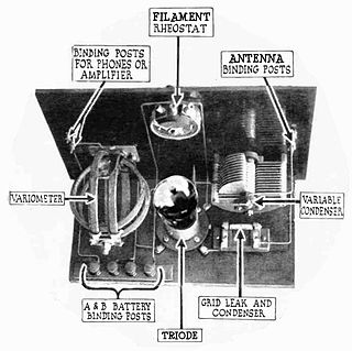
A triode is an electronic amplifying vacuum tube consisting of three electrodes inside an evacuated glass envelope: a heated filament or cathode, a grid, and a plate (anode). Developed from Lee De Forest's 1906 Audion, a partial vacuum tube that added a grid electrode to the thermionic diode, the triode was the first practical electronic amplifier and the ancestor of other types of vacuum tubes such as the tetrode and pentode. Its invention founded the electronics age, making possible amplified radio technology and long-distance telephony. Triodes were widely used in consumer electronics devices such as radios and televisions until the 1970s, when transistors replaced them. Today, their main remaining use is in high-power RF amplifiers in radio transmitters and industrial RF heating devices. In recent years there has been a resurgence in demand for low power triodes due to renewed interest in tube-type audio systems by audiophiles who prefer the pleasantly (warm) distorted sound of tube-based electronics.
The metal–oxide–semiconductor field-effect transistor is a type of field-effect transistor (FET), most commonly fabricated by the controlled oxidation of silicon. It has an insulated gate, the voltage of which determines the conductivity of the device. This ability to change conductivity with the amount of applied voltage can be used for amplifying or switching electronic signals. A metal-insulator-semiconductor field-effect transistor (MISFET) is a term almost synonymous with MOSFET. Another synonym is IGFET for insulated-gate field-effect transistor.
The junction-gate field-effect transistor (JFET) is one of the simplest types of field-effect transistor. JFETs are three-terminal semiconductor devices that can be used as electronically controlled switches or resistors, or to build amplifiers.
The Hartley oscillator is an electronic oscillator circuit in which the oscillation frequency is determined by a tuned circuit consisting of capacitors and inductors, that is, an LC oscillator. The circuit was invented in 1915 by American engineer Ralph Hartley. The distinguishing feature of the Hartley oscillator is that the tuned circuit consists of a single capacitor in parallel with two inductors in series, and the feedback signal needed for oscillation is taken from the center connection of the two inductors.
A current mirror is a circuit designed to copy a current through one active device by controlling the current in another active device of a circuit, keeping the output current constant regardless of loading. The current being "copied" can be, and sometimes is, a varying signal current. Conceptually, an ideal current mirror is simply an ideal inverting current amplifier that reverses the current direction as well. Or it can consist of a current-controlled current source (CCCS). The current mirror is used to provide bias currents and active loads to circuits. It can also be used to model a more realistic current source.
Transconductance, also infrequently called mutual conductance, is the electrical characteristic relating the current through the output of a device to the voltage across the input of a device. Conductance is the reciprocal of resistance.
A current source is an electronic circuit that delivers or absorbs an electric current which is independent of the voltage across it.
The cascode is a two-stage amplifier that consists of a common-emitter stage feeding into a common-base stage.
A grid leak detector is an electronic circuit that demodulates an amplitude modulated alternating current and amplifies the recovered modulating voltage. The circuit utilizes the non-linear cathode to control grid conduction characteristic and the amplification factor of a vacuum tube. Invented by Lee De Forest around 1912, it was used as the detector (demodulator) in the first vacuum tube radio receivers until the 1930s.
In electronics, noise is an unwanted disturbance in an electrical signal.
Flicker noise is a type of electronic noise with a 1/f power spectral density. It is therefore often referred to as 1/f noise or pink noise, though these terms have wider definitions. It occurs in almost all electronic devices and can show up with a variety of other effects, such as impurities in a conductive channel, generation and recombination noise in a transistor due to base current, and so on.
In electronics, biasing is the setting of DC operating conditions of an active device in an amplifier. Many electronic devices, such as diodes, transistors and vacuum tubes, whose function is processing time-varying (AC) signals, also require a steady (DC) current or voltage at their terminals to operate correctly. This current or voltage is called bias. The AC signal applied to them is superposed on this DC bias current or voltage.
A valve RF amplifier or tube amplifier (U.S.) is a device for electrically amplifying the power of an electrical radio frequency signal.
Technical specifications and detailed information on the valve audio amplifier, including its development history.
SN76477 "complex sound generator" is a sound chip produced by Texas Instruments (TI). The chip came to market in 1978, and TI ceased production of the part. A compatible version is identified as ICS76477. The chip is typically used as a sound effects generator in arcade games and toys and for hobby projects. The use of the SN76477 in a musical context is limited by the fact that it was difficult to electronically control the pitch of the produced sound.
The field-effect transistor (FET) is a type of transistor that uses an electric field to control the flow of current in a semiconductor. FETs are devices with three terminals: source, gate, and drain. FETs control the flow of current by the application of a voltage to the gate, which in turn alters the conductivity between the drain and source.
The NE5532, also sold as SA5532, SE5532 and NG5532 is a dual monolithic, bipolar, internally compensated operational amplifier for audio applications introduced by Signetics in 1979. The 5532 and the contemporary TL072 were the first operational amplifiers that outperformed discrete class A circuits in professional audio applications. Due to low noise and very low distortion, the 5532 became the industry standard for professional audio. According to Douglas Self, "there is probably no music on the planet that has not passed through a hundred or more 5532s on its way to the consumer". The performance of the 5532 remained best in class for almost thirty years, until the introduction of the LM4562 in 2007. As of 2021, the 5532 remains in mass production as a generic product.
References
↑ Jafaripahah, M.; Al-Hashimi, B. M.; White, N. M. (2004, May). Design Consideration and Implementation of Analog Adaptive Filters for Sensor Response Correction. Proceedings of the ICEE2004.
↑ Greason, Jeffrey K. (1983). Voltage-Controlled Resistance Element With Superior Dynamic Range. U.S. Patent US 5264785 A US 5264785 A.
↑ Wee, Keng Hoongl; Sarpeshkar, Rahul (1986) JFET Ohmic Differential Amplifier, Keithley Instruments, U.S. Patent.
↑ Schneider, Leif E.; Thompson, Kevin D. (2014). Self-optimizing Energy Harvester Using Generator Having a Variable Source Voltage. Perpetua Power Source Technologies, Inc. U.S. Patent US 8664931 B2.
↑ Madaffari, Peter L. (2000). Amplifier with Reduced Input Capacitance. Tibbetts Industries, inc. U.S. Patent US 6023194 A.
↑ Ballenger, Matthew; Kendrick, George (2006). Lamp With Integral Voltage Converter Having Phase-Controlled Dimming Circuit Containing a Voltage Controlled Resistor. Osram Sylvania, Inc. U.S. Patent, US 20060082320 A1.
↑ Stoffer, C. Daniel W (1971). Balanced Modulator With JFET's Voltage Controlled Resistors. Collins Radio Company, U.S. Patent US 3621473 A.
↑ Sung-Dae, Lee; Won-Hyo, Lee; Kang-Min, Chung (1998). A Highly Linear Voltage Controlled Resistor for Neural Chip. Systems, Man, and Cybernetics, 1998. 1998 IEEE International Conference.
↑ Molina, Johnnie F.; Stitt II, Mark; R., Burt, Rodney. (1994). Programmable Gain Amplifier Circuitry and Method for Biasing JFET Gain Switches Thereof Burr-Brown. U.S. Patent US 5327098 A.
↑ Tsai, Tsung-Hsien; Hung, Tsung-Hsien, Chen, Chien-Hung; Yuan, Min-Shueh (2010) Phase Lock Loop (PLL) with Gain Control. Taiwan Semiconductor Manufacturing Company. U.S. Patent US7786771 B2.
↑ Ballenger, Matthew B; Kendrick, George B. (2010). Lamp With Integral Voltage Converter Having Phase-Controlled Dimming Circuit Containing a Voltage Controlled Resistor. Osram Sylvania Inc., U.S. Patent US 7839095 B2.
↑ FETs as Voltage Controlled Resistors, (1997, March). Vishay.
↑ McCarthy, Daniel P.; Connell, Lawrence E; Hollenbeck, Neal W. (2009) Linear Voltage Controlled Variable Attenuator With Linear db/v Gain Slope. FreeScale Semiconductor. U.S. Patent US 20090143036 A1.
↑ Griffen, Jed D. (2002). Highly Accurate Voltage Controlled Oscillator With RC Circuit. Intel Corp. U.S. Patent US 6498539 B2.
↑ High-Voltage Electric Stimulation Apparatus for Plants (2012). 西藏农牧科学院蔬菜研究所 China Patent CN 202285631 U.
↑ Symons, Pete (2013). Digital Waveform Generation. Cambridge University Press. P. 33.
↑ Maxwell, John (1976), AN-6602Low Noise JFET – The Noise Problem Solver. Fairchild Semiconductor.
↑ Levinzon, Felix (2014). Piezoelectric Accelerometers with Integral Electronics. Springer, P. 75.
↑ Yang, Eric; Milic, Ognjen; Zhou, Jinghai (2011, Nov), Input Surge Protection Device Using JFET, Monolithic Power Systems, Inc. U.S. Patent US 8068321 B2.
↑ Roundree, Robert Newton (2014, Nov). JFET ESD Protection Circuit for low Voltage Applications. U.S. Patent US 20140339608 A1.
↑ FETs as Voltage Controlled Resistors, (1997, March). Vishay.
↑ FETs as Voltage Controlled Resistors, (1997, March). Vishay.
↑ Wee, Keng Hoongl; Sarpeshkar, Rahul (1986) JFET Ohmic Differential Amplifier, Keithley Instruments, U.S. Patent
↑ Holani, Rani; Pandey, Prem C; Tiwari, Nitya (2014). A JFET-based Circuit For Realizing a Precision and linear Floating Voltage-Controlled Resistance, 2014 Annual IEEE India Conference (INDICON).
↑ Liao, Yihua. Neural Networks in Hardware: A Survey, Analog Neurochips, Section 5.3.2, University of California Davis.
↑ Zhang, Xiaolin; Maeda, Yoshinori (2012). Nerve Equivalent Circuit Synapse Equivalent Circuit and Nerve Cell Body Tokyo Institute of Technology. U.S. Patent US 8112373 B2.
↑ Rice University (2016, June), RedEye could let your phone see 24-7. Science Daily.
↑ Quan, Ron. A Guide to Using Sensors JFET for Sensor Applications. Linear Systems.
This page is based on this Wikipedia article Text is available under the CC BY-SA 4.0 license; additional terms may apply. Images, videos and audio are available under their respective licenses.