
An oil well is a drillhole boring in Earth that is designed to bring petroleum oil hydrocarbons to the surface. Usually some natural gas is released as associated petroleum gas along with the oil. A well that is designed to produce only gas may be termed a gas well. Wells are created by drilling down into an oil or gas reserve that is then mounted with an extraction device such as a pumpjack which allows extraction from the reserve. Creating the wells can be an expensive process, costing at least hundreds of thousands of dollars, and costing much more when in hard to reach areas, e.g., when creating offshore oil platforms. The process of modern drilling for wells first started in the 19th century, but was made more efficient with advances to oil drilling rigs during the 20th century.
Well logging, also known as borehole logging is the practice of making a detailed record of the geologic formations penetrated by a borehole. The log may be based either on visual inspection of samples brought to the surface or on physical measurements made by instruments lowered into the hole. Some types of geophysical well logs can be done during any phase of a well's history: drilling, completing, producing, or abandoning. Well logging is performed in boreholes drilled for the oil and gas, groundwater, mineral and geothermal exploration, as well as part of environmental and geotechnical studies.
A petroleum reservoir or oil and gas reservoir is a subsurface accumulation of hydrocarbons contained in porous or fractured rock formations.
A wet gas is any gas with a small amount of liquid present. The term "wet gas" has been used to describe a range of conditions varying from a humid gas which is gas saturated with liquid vapour to a multiphase flow with a 90% volume of gas. There has been some debate as to its actual definition, and there is currently no fully defined quantitative definition of a wet gas flow that is universally accepted.

In fluid mechanics, multiphase flow is the simultaneous flow of materials with two or more thermodynamic phases. Virtually all processing technologies from cavitating pumps and turbines to paper-making and the construction of plastics involve some form of multiphase flow. It is also prevalent in many natural phenomena.
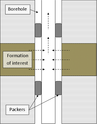
A drill stem test (DST) is a procedure for isolating and testing the pressure, permeability and productive capacity of a geological formation during the drilling of a well. The test is an important measurement of pressure behaviour at the drill stem and is a valuable way of obtaining information on the formation fluid and establishing whether a well has found a commercial hydrocarbon reservoir.
Reservoir engineering is a branch of petroleum engineering that applies scientific principles to the fluid flow through a porous medium during the development and production of oil and gas reservoirs so as to obtain a high economic recovery. The working tools of the reservoir engineer are subsurface geology, applied mathematics, and the basic laws of physics and chemistry governing the behavior of liquid and vapor phases of crude oil, natural gas, and water in reservoir rock. Of particular interest to reservoir engineers is generating accurate reserves estimates for use in financial reporting to the SEC and other regulatory bodies. Other job responsibilities include numerical reservoir modeling, production forecasting, well testing, well drilling and workover planning, economic modeling, and PVT analysis of reservoir fluids. Reservoir engineers also play a central role in field development planning, recommending appropriate and cost-effective reservoir depletion schemes such as waterflooding or gas injection to maximize hydrocarbon recovery. Due to legislative changes in many hydrocarbon-producing countries, they are also involved in the design and implementation of carbon sequestration projects in order to minimise the emission of greenhouse gases.
Geosteering is the optimal placement of a wellbore based on the results of realtime downhole geological and geophysical logging measurements rather than three-dimensional targets in space. The objective is usually to keep a directional wellbore within a hydrocarbon pay zone defined in terms of its resistivity, density or even biostratigraphy. In mature areas, geosteering may be used to keep a wellbore in a particular reservoir section to minimize gas or water breakthrough and maximize economic production from the well. In the process of drilling a borehole, geosteering is the act of adjusting the borehole position on the fly to reach one or more geological targets. These changes are based on geological information gathered while drilling.
Petrophysics is the study of physical and chemical rock properties and their interactions with fluids.
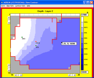
Reservoir simulation is an area of reservoir engineering in which computer models are used to predict the flow of fluids through porous media.
A multiphase flow meter is a device used to measure the individual phase flow rates of constituent phases in a given flow where oil, water and gas mixtures are initially co-mingled together during the oil production processes.

The Schiehallion oilfield is a deepwater offshore oilfield approximately 175 kilometres (110 mi) west of the Shetland Islands in the North Atlantic Ocean. The Schiehallion and adjacent Loyal field were jointly developed by BP on behalf of the Schiehallion field partners; BP, Shell, Amerada Hess, Murphy Oil, Statoil and OMV, and the Loyal field partners; BP and Shell.
An oil production plant is a facility which processes production fluids from oil wells in order to separate out key components and prepare them for export. Typical oil well production fluids are a mixture of oil, gas and produced water. An oil production plant is distinct from an oil depot, which does not have processing facilities.
The term separator in oilfield terminology designates a pressure vessel used for separating well fluids produced from oil and gas wells into gaseous and liquid components. A separator for petroleum production is a large vessel designed to separate production fluids into their constituent components of oil, gas and water. A separating vessel may be referred to in the following ways: Oil and gas separator, Separator, Stage separator, Trap, Knockout vessel, Flash chamber, Expansion separator or expansion vessel, Scrubber, Filter. These separating vessels are normally used on a producing lease or platform near the wellhead, manifold, or tank battery to separate fluids produced from oil and gas wells into oil and gas or liquid and gas. An oil and gas separator generally includes the following essential components and features:
- A vessel that includes (a) primary separation device and/or section, (b) secondary "gravity" settling (separating) section, (c) mist extractor to remove small liquid particles from the gas, (d) gas outlet, (e) liquid settling (separating) section to remove gas or vapor from oil, (f) oil outlet, and (g) water outlet.
- Adequate volumetric liquid capacity to handle liquid surges (slugs) from the wells and/or flowlines.
- Adequate vessel diameter and height or length to allow most of the liquid to separate from the gas so that the mist extractor will not be flooded.
- A means of controlling an oil level in the separator, which usually includes a liquid-level controller and a diaphragm motor valve on the oil outlet.
- A back pressure valve on the gas outlet to maintain a steady pressure in the vessel.
- Pressure relief devices.
In 2017 the department was merged with the Department of Geology and Mineral Resources Engineering, forming the new Department of Geoscience and Petroleum.
Roxar AS was a provider of products and associated services for reservoir management and production optimisation in the upstream oil and gas industry. Roxar was headquartered in Stavanger, Norway and operated in 19 countries with around 900 employees. Roxar offered software for reservoir interpretation, modelling and simulation, as well as instrumentation for well planning, monitoring, metering and production optimisation. Roxar was acquired by Emerson Electric Company in April 2009.
In the petroleum industry, allocation refers to practices of breaking down measures of quantities of extracted hydrocarbons across various contributing sources. Allocation aids the attribution of ownerships of hydrocarbons as each contributing element to a commingled flow or to a storage of petroleum may have a unique ownership. Contributing sources in this context are typically producing petroleum wells delivering flows of petroleum or flows of natural gas to a commingled flow or storage.
In petroleum science, reservoir fluids are the fluids mixture contained within the petroleum reservoir which technically are placed in the reservoir rock. Reservoir fluids normally include liquid hydrocarbon, aqueous solutions with dissolved salt, hydrocarbon and non-hydrocarbon gases such as methane and hydrogen sulfide respectively.
Electrical capacitance volume tomography (ECVT) is a non-invasive 3D imaging technology applied primarily to multiphase flows. It was first introduced by W. Warsito, Q. Marashdeh, and L.-S. Fan as an extension of the conventional electrical capacitance tomography (ECT). In conventional ECT, sensor plates are distributed around a surface of interest. Measured capacitance between plate combinations is used to reconstruct 2D images (tomograms) of material distribution. In ECT, the fringing field from the edges of the plates is viewed as a source of distortion to the final reconstructed image and is thus mitigated by guard electrodes. ECVT exploits this fringing field and expands it through 3D sensor designs that deliberately establish an electric field variation in all three dimensions. The image reconstruction algorithms are similar in nature to ECT; nevertheless, the reconstruction problem in ECVT is more complicated. The sensitivity matrix of an ECVT sensor is more ill-conditioned and the overall reconstruction problem is more ill-posed compared to ECT. The ECVT approach to sensor design allows direct 3D imaging of the outrounded geometry. This is different than 3D-ECT that relies on stacking images from individual ECT sensors. 3D-ECT can also be accomplished by stacking frames from a sequence of time intervals of ECT measurements. Because the ECT sensor plates are required to have lengths on the order of the domain cross-section, 3D-ECT does not provide the required resolution in the axial dimension. ECVT solves this problem by going directly to the image reconstruction and avoiding the stacking approach. This is accomplished by using a sensor that is inherently three-dimensional.

