Related Research Articles
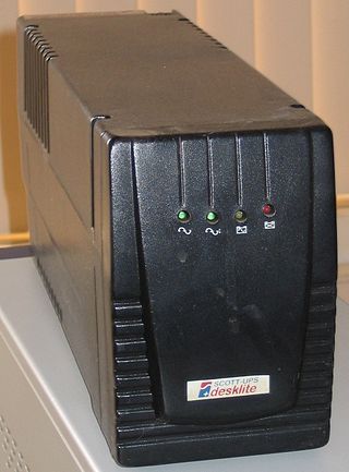
An uninterruptible power supply (UPS) or uninterruptible power source is a type of continual power system that provides automated backup electric power to a load when the input power source or mains power fails. A UPS differs from a traditional auxiliary/emergency power system or standby generator in that it will provide near-instantaneous protection from input power interruptions by switching to energy stored in battery packs, supercapacitors or flywheels. The on-battery run-times of most UPSs are relatively short but sufficient to "buy time" for initiating a standby power source or properly shutting down the protected equipment. Almost all UPSs also contain integrated surge protection to shield the output appliances from voltage spikes.

A power supply is an electrical device that supplies electric power to an electrical load. The main purpose of a power supply is to convert electric current from a source to the correct voltage, current, and frequency to power the load. As a result, power supplies are sometimes referred to as electric power converters. Some power supplies are separate standalone pieces of equipment, while others are built into the load appliances that they power. Examples of the latter include power supplies found in desktop computers and consumer electronics devices. Other functions that power supplies may perform include limiting the current drawn by the load to safe levels, shutting off the current in the event of an electrical fault, power conditioning to prevent electronic noise or voltage surges on the input from reaching the load, power-factor correction, and storing energy so it can continue to power the load in the event of a temporary interruption in the source power.

An alternator is an electrical generator that converts mechanical energy to electrical energy in the form of alternating current. For reasons of cost and simplicity, most alternators use a rotating magnetic field with a stationary armature. Occasionally, a linear alternator or a rotating armature with a stationary magnetic field is used. In principle, any AC electrical generator can be called an alternator, but usually the term refers to small rotating machines driven by automotive and other internal combustion engines.

A power inverter, inverter or invertor is a power electronic device or circuitry that changes direct current (DC) to alternating current (AC). The resulting AC frequency obtained depends on the particular device employed. Inverters do the opposite of rectifiers which were originally large electromechanical devices converting AC to DC.

Regenerative braking is an energy recovery mechanism that slows down a moving vehicle or object by converting its kinetic energy into a form that can be either used immediately or stored until needed. In this mechanism, the electric traction motor uses the vehicle's momentum to recover energy that would otherwise be lost to the brake discs as heat. This method contrasts with conventional braking systems. In those systems, the excess kinetic energy is converted to unwanted and wasted heat due to friction in the brakes, or with rheostatic brakes, where the energy is recovered by using electric motors as generators but is immediately dissipated as heat in resistors. In addition to improving the overall efficiency of the vehicle, regeneration can significantly extend the life of the braking system as the mechanical parts will not wear out quickly.

A diesel locomotive is a type of railway locomotive in which the power source is a diesel engine. Several types of diesel locomotives have been developed, differing mainly in the means by which mechanical power is conveyed to the driving wheels. The most common are diesel-electric locomotives and diesel-hydraulic.

An electric locomotive is a locomotive powered by electricity from overhead lines, a third rail or on-board energy storage such as a battery or a supercapacitor. Locomotives with on-board fuelled prime movers, such as diesel engines or gas turbines, are classed as diesel-electric or gas turbine-electric and not as electric locomotives, because the electric generator/motor combination serves only as a power transmission system.

Dynamic braking is the use of an electric traction motor as a generator when slowing a vehicle such as an electric or diesel-electric locomotive. It is termed "rheostatic" if the generated electrical power is dissipated as heat in brake grid resistors, and "regenerative" if the power is returned to the supply line. Dynamic braking reduces wear on friction-based braking components, and regeneration lowers net energy consumption. Dynamic braking may also be used on railcars with multiple units, light rail vehicles, electric trams, trolleybuses, and electric and hybrid electric automobiles.
A DC-to-DC converter is an electronic circuit or electromechanical device that converts a source of direct current (DC) from one voltage level to another. It is a type of electric power converter. Power levels range from very low to very high.

A traction motor is an electric motor used for propulsion of a vehicle, such as locomotives, electric or hydrogen vehicles, or electric multiple unit trains.
A motor–generator is a device for converting electrical power to another form. Motor–generator sets are used to convert frequency, voltage, or phase of power. They may also be used to isolate electrical loads from the electrical power supply line. Large motor–generators were widely used to convert industrial amounts of power while smaller motor–generators were used to convert battery power to higher DC voltages.

The term All American Five is a colloquial name for mass-produced, superheterodyne radio receivers that used five vacuum tubes in their design. These radio sets were designed to receive amplitude modulation (AM) broadcasts in the medium wave band, and were manufactured in the United States from the mid-1930s until the early 1960s. By eliminating a power transformer, cost of the units was kept low; the same principle was later applied to television receivers. Variations in the design for lower cost, shortwave bands, better performance or special power supplies existed, although many sets used an identical set of vacuum tubes.
Hybrid Synergy Drive (HSD), also known as Toyota Hybrid System II, is the brand name of Toyota Motor Corporation for the hybrid car drive train technology used in vehicles with the Toyota and Lexus marques. First introduced on the Prius, the technology is an option on several other Toyota and Lexus vehicles and has been adapted for the electric drive system of the hydrogen-powered Mirai, and for a plug-in hybrid version of the Prius. Previously, Toyota also licensed its HSD technology to Nissan for use in its Nissan Altima Hybrid. Its parts supplier Aisin Seiki Co. offers similar hybrid transmissions to other car companies.

In rail transport, head-end power (HEP), also known as electric train supply (ETS), is the electrical power distribution system on a passenger train. The power source, usually a locomotive at the front or 'head' of a train, provides the electricity used for heating, lighting, electrical and other 'hotel' needs. The maritime equivalent is hotel electric power. A successful attempt by the London, Brighton and South Coast Railway in October 1881 to light the passenger cars on the London to Brighton route heralded the beginning of using electricity to light trains in the world.

The British Rail Class 74 was an electro-diesel locomotive that operated on the Southern Region of British Railways, rebuilt from redundant Class 71 locomotives in the late 1960s. An electro-diesel locomotive is one that can operate either from an electrical supply, such as overhead catenary or an energised third rail, or from an onboard diesel engine. All were withdrawn between June 1976 and December 1977, and scrapped between 1977 and 1981.

An emergency power system is an independent source of electrical power that supports important electrical systems on loss of normal power supply. A standby power system may include a standby generator, batteries and other apparatus. Emergency power systems are installed to protect life and property from the consequences of loss of primary electric power supply. It is a type of continual power system.
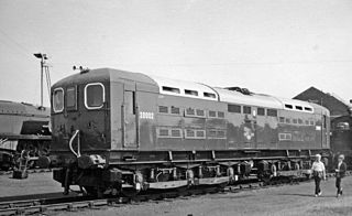
The British Rail Class 70 was a class of three third rail Co-Co electric locomotives. The initial two were built by the Southern Railway (SR) at Ashford Works in 1940–41 and 1945 and were numbered CC1 and CC2 - the Southern Railway latterly preferring French practice for locomotive numbers which also gave an indication of the wheel arrangement. Electrical equipment was designed by Alfred Raworth and the body and bogies by Oliver Bulleid. CC2 was modified slightly from the original design by C. M. Cock who had succeeded Raworth as Electrical Engineer. The third was built by British Railways in 1948 and numbered 20003.
Hybrid vehicle drivetrains transmit power to the driving wheels for hybrid vehicles. A hybrid vehicle has multiple forms of motive power.
A brushed DC electric motor is an internally commutated electric motor designed to be run from a direct current power source and utilizing an electric brush for contact.
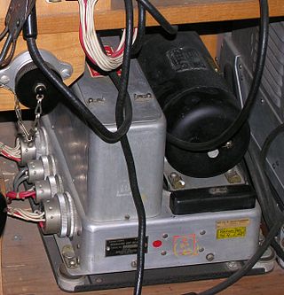
A metadyne is a direct current electrical machine with two pairs of brushes. It can be used as an amplifier or rotary transformer. It is similar to a third brush dynamo but has additional regulator or "variator" windings. It is also similar to an amplidyne except that the latter has a compensating winding which fully counteracts the effect of the flux produced by the load current. The technical description is "a cross-field direct current machine designed to utilize armature reaction". A metadyne can convert a constant-voltage input into a constant-current, variable-voltage output.
References
- ↑ Elliott, T. C., Electric Accumulator Manual, George Newnes Ltd, London, 1948, page 29
- ↑ Cooper, B. K., Electric Trains and Locomotives, Leonard Hill Ltd, London, 1954, pp 35–38
- ↑ Cooper, B. K., Electric Trains and Locomotives, Leonard Hill Ltd, London, 1954, page 38
- ↑ R.R. Gulati,Monochrome And Colour Television, New Age International, 2006 ISBN 8122417760, page 582