Slope stability analysis is a static or dynamic, analytical or empirical method to evaluate the stability of slopes of soil- and rock-fill dams, embankments, excavated slopes, and natural slopes in soil and rock. It is performed to assess the safe design of a human-made or natural slopes (e.g. embankments, road cuts, open-pit mining, excavations, landfills etc.) and the equilibrium conditions.[1][2]Slope stability is the resistance of inclined surface to failure by sliding or collapsing.[3] The main objectives of slope stability analysis are finding endangered areas, investigation of potential failure mechanisms, determination of the slope sensitivity to different triggering mechanisms, designing of optimal slopes with regard to safety, reliability and economics, and designing possible remedial measures, e.g. barriers and stabilization.[1][2]
Successful design of the slope requires geological information and site characteristics, e.g. properties of soil/rock mass, slope geometry, groundwater conditions, alternation of materials by faulting, joint or discontinuity systems, movements and tension in joints, earthquake activity etc.[4][5] The presence of water has a detrimental effect on slope stability. Water pressure acting in the pore spaces, fractures or other discontinuities in the materials that make up the pit slope will reduce the strength of those materials.[6] Choice of correct analysis technique depends on both site conditions and the potential mode of failure, with careful consideration being given to the varying strengths, weaknesses and limitations inherent in each methodology.[7]
Before the computer age stability analysis was performed graphically or by using a hand-held calculator. Today engineers have a lot of possibilities to use analysis software, ranges from simple limit equilibrium techniques through to computational limit analysis approaches (e.g. Finite element limit analysis, Discontinuity layout optimization) to complex and sophisticated numerical solutions (finite-/distinct-element codes).[1] The engineer must fully understand limitations of each technique. For example, limit equilibrium is most commonly used and simple solution method, but it can become inadequate if the slope fails by complex mechanisms (e.g. internal deformation and brittle fracture, progressive creep, liquefaction of weaker soil layers, etc.). In these cases more sophisticated numerical modelling techniques should be utilised. Also, even for very simple slopes, the results obtained with typical limit equilibrium methods currently in use (Bishop, Spencer, etc.) may differ considerably. In addition, the use of the risk assessment concept is increasing today. Risk assessment is concerned with both the consequence of slope failure and the probability of failure (both require an understanding of the failure mechanism).[8][9]
Limit equilibrium analysis
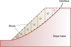
A typical cross-section of a slope used in two-dimensional analyses.
Conventional methods of slope stability analysis can be divided into three groups: kinematic analysis, limit equilibrium analysis, and rockfall simulators.[10] Most slope stability analysis computer programs are based on the limit equilibrium concept for a two- or three-dimensional model.[11][12] Two-dimensional sections are analyzed assuming plane strain conditions. Stability analyses of two-dimensional slope geometries using simple analytical approaches can provide important insights into the initial design and risk assessment of slopes.
Limit equilibrium methods investigate the equilibrium of a soil mass tending to slide down under the influence of gravity. Translational or rotational movement is considered on an assumed or known potential slip surface below the soil or rock mass.[13] In rock slope engineering, methods may be highly significant to simple block failure along distinct discontinuities.[10] All these methods are based on the comparison of forces, moments, or stresses resisting movement of the mass with those that can cause unstable motion (disturbing forces). The output of the analysis is a factor of safety, defined as the ratio of the shear strength (or, alternatively, an equivalent measure of shear resistance or capacity) to the shear stress (or other equivalent measure) required for equilibrium. If the value of factor of safety is less than 1.0, the slope is unstable.
All limit equilibrium methods assume that the shear strengths of the materials along the potential failure surface are governed by linear (Mohr-Coulomb) or non-linear relationships between shear strength and the normal stress on the failure surface.[13] The most commonly used variation is Terzaghi's theory of shear strength which states that
where is the shear strength of the interface, is the effective stress ( is the total stress normal to the interface and is the pore water pressure on the interface), is the effective friction angle, and is the effective cohesion.
The methods of slices is the most popular limit equilibrium technique. In this approach, the soil mass is discretized into vertical slices.[12][14] Several versions of the method are in use. These variations can produce different results (factor of safety) because of different assumptions and inter-slice boundary conditions.[13][15]
The location of the interface is typically unknown but can be found using numerical optimization methods.[16] For example, functional slope design considers the critical slip surface to be the location where that has the lowest value of factor of safety from a range of possible surfaces. A wide variety of slope stability software use the limit equilibrium concept with automatic critical slip surface determination.
Typical slope stability software can analyze the stability of generally layered soil slopes, embankments, earth cuts, and anchored sheeting structures. Earthquake effects, external loading, groundwater conditions, stabilization forces (i.e., anchors, geo-reinforcements etc.) can also be included.
Analytical techniques: Method of slices
Schematic of the method of slices showing rotation center.
Many slope stability analysis tools use various versions of the methods of slices such as Bishop simplified, Ordinary method of slices (Swedish circle method/Petterson/Fellenius), Spencer, Sarma etc. Sarma and Spencer are called rigorous methods because they satisfy all three conditions of equilibrium: force equilibrium in horizontal and vertical direction and moment equilibrium condition. Rigorous methods can provide more accurate results than non-rigorous methods. Bishop simplified or Fellenius are non-rigorous methods satisfying only some of the equilibrium conditions and making some simplifying assumptions.[14][15] Some of these approaches are discussed below.
Swedish Slip Circle Method of Analysis
The Swedish Slip Circle method assumes that the friction angle of the soil or rock is equal to zero, i.e., . In other words, when friction angle is considered to be zero, the effective stress term goes to zero, thus equating the shear strength to the cohesion parameter of the given soil. The Swedish slip circle method assumes a circular failure interface, and analyzes stress and strength parameters using circular geometry and statics. The moment caused by the internal driving forces of a slope is compared to the moment caused by forces resisting slope failure. If resisting forces are greater than driving forces, the slope is assumed stable.
Ordinary Method of Slices
Division of the slope mass in the method of slices.
In the method of slices, also called OMS or the Fellenius method, the sliding mass above the failure surface is divided into a number of slices. The forces acting on each slice are obtained by considering the mechanical (force and moment) equilibrium for the slices. Each slice is considered on its own and interactions between slices are neglected because the resultant forces are parallel to the base of each slice. However, Newton's third law is not satisfied by this method because, in general, the resultants on the left and right of a slice do not have the same magnitude and are not collinear.[17]
This allows for a simple static equilibrium calculation, considering only soil weight, along with shear and normal stresses along the failure plane. Both the friction angle and cohesion can be considered for each slice. In the general case of the method of slices, the forces acting on a slice are shown in the figure below. The normal () and shear () forces between adjacent slices constrain each slice and make the problem statically indeterminate when they are included in the computation.
Force equilibrium for a slice in the method of slices. The block is assumed to have thickness . The slices on the left and right exert normal forces and shear forces , the weight of the slice causes the force . These forces are balanced by the pore pressure and reactions of the base .
For the ordinary method of slices, the resultant vertical and horizontal forces are
where represents a linear factor that determines the increase in horizontal force with the depth of the slice. Solving for gives
Next, the method assumes that each slice can rotate about a center of rotation and that moment balance about this point is also needed for equilibrium. A balance of moments for all the slices taken together gives
where is the slice index, are the moment arms, and loads on the surface have been ignored. The moment equation can be used to solve for the shear forces at the interface after substituting the expression for the normal force:
Using Terzaghi's strength theory and converting the stresses into moments, we have
where is the pore pressure. The factor of safety is the ratio of the maximum moment from Terzaghi's theory to the estimated moment,
Modified Bishop's Method of Analysis
The Modified Bishop's method[18] is slightly different from the ordinary method of slices in that normal interaction forces between adjacent slices are assumed to be collinear and the resultant interslice shear force is zero. The approach was proposed by Alan W. Bishop of Imperial College. The constraint introduced by the normal forces between slices makes the problem statically indeterminate. As a result, iterative methods have to be used to solve for the factor of safety. The method has been shown to produce factor of safety values within a few percent of the "correct" values.
The factor of safety for moment equilibrium in Bishop's method can be expressed as
where
where, as before, is the slice index, is the effective cohesion, is the effective internal angle of internal friction, is the width of each slice, is the weight of each slice, and is the water pressure at the base of each slice. An iterative method has to be used to solve for because the factor of safety appears both on the left and right hand sides of the equation.
Lorimer's method
Lorimer's Method is a technique for evaluating slope stability in cohesive soils. It differs from Bishop's Method in that it uses a clothoid slip surface in place of a circle. This mode of failure was determined experimentally to account for effects of particle cementation. The method was developed in the 1930s by Gerhardt Lorimer (Dec 20, 1894-Oct 19, 1961), a student of geotechnical pioneer Karl von Terzaghi.
Spencer's Method
Spencer's Method of analysis[19] requires a computer program capable of cyclic algorithms, but makes slope stability analysis easier. Spencer's algorithm satisfies all equilibria (horizontal, vertical and driving moment) on each slice. The method allows for unconstrained slip plains and can therefore determine the factor of safety along any slip surface. The rigid equilibrium and unconstrained slip surface result in more precise safety factors than, for example, Bishop's Method or the Ordinary Method of Slices.[19]
The Sarma method,[20] proposed by Sarada K. Sarma of Imperial College is a Limit equilibrium technique used to assess the stability of slopes under seismic conditions. It may also be used for static conditions if the value of the horizontal load is taken as zero. The method can analyse a wide range of slope failures as it may accommodate a multi-wedge failure mechanism and therefore it is not restricted to planar or circular failure surfaces. It may provide information about the factor of safety or about the critical acceleration required to cause collapse.
Comparisons
The assumptions made by a number of limit equilibrium methods are listed in the table below.[21]
The direction of the resultant interslice forces is defined using an arbitrary function. The fractions of the function value needed for force and moment balance is computed.
The resultant interslice force is either parallel to the ground surface or equal to the average slope from the beginning to the end of the slip surface..
The shear strength criterion is applied to the shears on the sides and bottom of each slice. The inclinations of the slice interfaces are varied until a critical criterion is met.
The table below shows the statical equilibrium conditions satisfied by some of the popular limit equilibrium methods.[21]
Method
Force balance (vertical)
Force balance (horizontal)
Moment balance
Ordinary MS
Yes
No
Yes
Bishop's simplified
Yes
No
Yes
Janbu's simplified
Yes
Yes
No
Janbu's generalized
Yes
Yes
Used to compute interslice shear forces
Spencer
Yes
Yes
Yes
Chugh
Yes
Yes
Yes
Morgenstern-Price
Yes
Yes
Yes
Fredlund-Krahn
Yes
Yes
Yes
Corps of Engineers
Yes
Yes
No
Lowe and Karafiath
Yes
Yes
No
Sarma
Yes
Yes
Yes
Rock slope stability analysis
Rock slope stability analysis based on limit equilibrium techniques may consider following modes of failures:
Planar failure -> case of rock mass sliding on a single surface (special case of general wedge type of failure); two-dimensional analysis may be used according to the concept of a block resisting on an inclined plane at limit equilibrium[27][28]
Polygonal failure -> sliding of a nature rock usually takes place on polygonally-shaped surfaces; calculation is based on a certain assumptions (e.g. sliding on a polygonal surface which is composed from N parts is kinematically possible only in case of development at least (N - 1) internal shear surfaces; rock mass is divided into blocks by internal shear surfaces; blocks are considered to be rigid; no tensile strength is permitted etc.)[28]
Wedge failure -> three-dimensional analysis enables modelling of the wedge sliding on two planes in a direction along the line of intersection[28][29]
Toppling failure -> long thin rock columns formed by the steeply dipping discontinuities may rotate about a pivot point located at the lowest corner of the block; the sum of the moments causing toppling of a block (i.e. horizontal weight component of the block and the sum of the driving forces from adjacent blocks behind the block under consideration) is compared to the sum of the moments resisting toppling (i.e. vertical weight component of the block and the sum of the resisting forces from adjacent blocks in front of the block under consideration); toppling occur if driving moments exceed resisting moments[30][31]
A more rigorous approach to slope stability analysis is limit analysis. Unlike limit equilibrium analysis which makes ad hoc though often reasonable assumptions, limit analysis is based on rigorous plasticity theory. This enables, among other things, the computation of upper and lower bounds on the true factor of safety.
Programs based on limit analysis include:
OptumG2 (2014-) General purpose software for geotechnical applications (also includes elastoplasticity, seepage, consolidation, staged construction, tunneling, and other relevant geotechnical analysis types).
LimitState:GEO (2008-) General purpose geotechnical software application based on Discontinuity layout optimization for plane strain problems including slope stability.
Kinematic analysis examines which modes of failure can possibly occur in the rock mass. Analysis requires the detailed evaluation of rock mass structure and the geometry of existing discontinuities contributing to block instability.[32][33]Stereographic representation (stereonets) of the planes and lines is used.[34] Stereonets are useful for analyzing discontinuous rock blocks.[35] Program DIPS allows for visualization structural data using stereonets, determination of the kinematic feasibility of rock mass and statistical analysis of the discontinuity properties.[32]
Rockfall simulators
Rock slope stability analysis may design protective measures near or around structures endangered by the falling blocks. Rockfall simulators determine travel paths and trajectories of unstable blocks separated from a rock slope face.[36]Analytical solution method described by Hungr & Evans[37] assumes rock block as a point with mass and velocity moving on a ballistic trajectory with regard to potential contact with slope surface. Calculation requires two restitution coefficients that depend on fragment shape, slope surface roughness, momentum and deformational properties and on the chance of certain conditions in a given impact.[38]
Numerical methods of analysis
Numerical modelling techniques provide an approximate solution to problems which otherwise cannot be solved by conventional methods, e.g. complex geometry, material anisotropy, non-linear behavior, in situ stresses. Numerical analysis allows for material deformation and failure, modelling of pore pressures, creep deformation, dynamic loading, assessing effects of parameter variations etc. However, numerical modelling is restricted by some limitations. For example, input parameters are not usually measured and availability of these data is generally poor. User also should be aware of boundary effects, meshing errors, hardware memory and time restrictions. Numerical methods used for slope stability analysis can be divided into three main groups: continuum, discontinuum and hybrid modelling.[39]
Modelling of the continuum is suitable for the analysis of soil slopes, massive intact rock or heavily jointed rock masses. This approach includes the finite-difference and finite element methods that discretize the whole mass to finite number of elements with the help of generated mesh (Fig. 3). In finite-difference method (FDM) differential equilibrium equations (i.e. strain-displacement and stress-strain relations) are solved. finite element method (FEM) uses the approximations to the connectivity of elements, continuity of displacements and stresses between elements.[40] Most of numerical codes allows modelling of discrete fractures, e.g. bedding planes, faults. Several constitutive models are usually available, e.g. elasticity, elasto-plasticity, strain-softening, elasto-viscoplasticity etc.[39]
Discontinuum approach is useful for rock slopes controlled by discontinuity behaviour. Rock mass is considered as an aggregation of distinct, interacting blocks subjected to external loads and assumed to undergo motion with time. This methodology is collectively called the discrete-element method (DEM). Discontinuum modelling allows for sliding between the blocks or particles. The DEM is based on solution of dynamic equation of equilibrium for each block repeatedly until the boundary conditions and laws of contact and motion are satisfied. Discontinuum modelling belongs to the most commonly applied numerical approach to rock slope analysis and following variations of the DEM exist:[39]
The distinct-element approach describes mechanical behaviour of both, the discontinuities and the solid material. This methodology is based on a force-displacement law (specifying the interaction between the deformable rock blocks) and a law of motion (determining displacements caused in the blocks by out-of-balance forces). Joints are treated as [boundary conditions. Deformable blocks are discretized into internal constant-strain elements.[39]
Discontinuum program UDEC[41] (Universal distinct element code) is suitable for high jointed rock slopes subjected to static or dynamic loading. Two-dimensional analysis of translational failure mechanism allows for simulating large displacements, modelling deformation or material yielding.[41] Three-dimensional discontinuum code 3DEC[42] contains modelling of multiple intersecting discontinuities and therefore it is suitable for analysis of wedge instabilities or influence of rock support (e.g. rockbolts, cables).[39]
In Discontinuous Deformation Analysis (DDA) displacements are unknowns and equilibrium equations are then solved analogous to finite element method. Each unit of finite element type mesh represents an isolated block bounded by discontinuities. Advantage of this methodology is possibility to model large deformations, rigid body movements, coupling or failure states between rock blocks.[39]
Discontinuous rock mass can be modelled with the help of distinct-element methodology in the form of particle flow code, e.g. program PFC2D/3D.[43][44] Spherical particles interact through frictional sliding contacts. Simulation of joint bounded blocks may be realized through specified bond strengths. Law of motion is repeatedly applied to each particle and force-displacement law to each contact. Particle flow methodology enables modelling of granular flow, fracture of intact rock, transitional block movements, dynamic response to blasting or seismicity, deformation between particles caused by shear or tensile forces. These codes also allow to model subsequent failure processes of rock slope, e.g. simulation of rock[39]
Hybrid/coupled modelling
Hybrid codes involve the coupling of various methodologies to maximize their key advantages, e.g. limit equilibrium analysis combined with finite element groundwater flow and stress analysis; coupled particle flow and finite-difference analyses; hydro-mechanically coupled finite element and material point methods for simulating the entire process of rainfall-induced landslides.[45] Hybrid techniques allows investigation of piping slope failures and the influence of high groundwater pressures on the failure of weak rock slope. Coupled finite-distinct-element codes provide for the modelling of both intact rock behavior and the development and behavior of fractures.
↑ Cardenas, IC (2019). "On the use of Bayesian networks as a meta-modelling approach to analyse uncertainties in slope stability analysis". Georisk: Assessment and Management of Risk for Engineered Systems and Geohazards. 13 (1): 53–65. Bibcode:2019GAMRE..13...53C. doi:10.1080/17499518.2018.1498524. S2CID216590427.
1 2 Janbu, Nilmar (1973), RC Hirschfeld; SJ Poulos (eds.), "Slope stability computations", In Embankment-dam Engineering, Jon Wiley and Sons Inc., NY: 40P
↑ Chugh, Ashok K (1982), "Slope stability analysis for earthquakes", International Journal for Numerical and Analytical Methods in Geomechanics, 6 (3): 307–322, Bibcode:1982IJNAM...6..307C, doi:10.1002/nag.1610060304
↑ "Slope Stability"(PDF). US Army Corps of Engineers. Retrieved 15 April 2015.
↑ Lowe, John; Karafiath, Leslie (1960), "Stability of earth dams upon drawdown", In Proc. 1st. Pan American Conference on Soil Mechanics and Foundation Engineering, México, 2: 537–552
Devoto, S.; Castelli, E. (September 2007). Slope stability in an old limestone quarry interested by a tourist project. 15th Meeting of the Association of European Geological Societies: Georesources Policy, Management, Environment. Tallinn.
Douw, W. (2009). Entwicklung einer Anordnung zur Nutzung von Massenschwerebewegungen beim Quarzitabbau im Rheinischen Schiefergebirge. Hackenheim, Germany: ConchBooks. p.358. ISBN978-3-939767-10-7.
Hack, H.R.G.K. (25–28 November 2002). "An evaluation of slope stability classification. Keynote Lecture.". In Dinis da Gama, C.; Ribeira e Sousa, L. (eds.). Proc. ISRM EUROCK'2002. Funchal, Madeira, Portugal: Sociedade Portuguesa de Geotecnia, Lisboa, Portugal. pp.3–32. ISBN972-98781-2-9.
Liu, Y.-C.; Chen, C.-S. (2005). "A new approach for application of rock mass classification on rock slope stability assessment". Engineering Geology. 89 (1–2): 129–143. doi:10.1016/j.enggeo.2006.09.017.
Pantelidis, L. (2009). "Rock slope stability assessment through rock mass classification systems". International Journal of Rock Mechanics and Mining Sciences. 46 (2, number 2): 315–325. Bibcode:2009IJRMM..46..315P. doi:10.1016/j.ijrmms.2008.06.003.
Singh, B.; Goel, R.K. (2002). Software for engineering control of landslide and tunnelling hazards. Vol.1. Taylor & Francis. p.358. ISBN978-90-5809-360-8.
Coduto, Donald P. (1998). Geotechnical Engineering: Principles and Practices. Prentice-Hall. ISBN0-13-576380-0
Fredlund, D. G., H. Rahardjo, M. D. Fredlund (2014). Unsaturated Soil Mechanics in Engineering Practice. Wiley-Interscience. ISBN978-1118133590
Yang, Xiao-Li; Li, L.; Yin, J.H. (2004), "Stability analysis of rock slopes with a modified Hoek-Brown failure criterion", International Journal for Numerical and Analytical Methods in Geomechanics, 28 (2), Chichester, Great Britain: John Wiley & Sons: 181–190, Bibcode:2004IJNAM..28..181Y, doi:10.1002/nag.330, ISSN0363-9061, S2CID120421002
Hungr, O.; Evans, S.G. (1988). "Engineering evaluation of fragmental rockfall hazards". In Bonnard, C. (ed.). Landslides. International Symposium on Landslides, Lausanne. Rotterdam: Balkema. pp.685–690.
This page is based on this Wikipedia article Text is available under the CC BY-SA 4.0 license; additional terms may apply. Images, videos and audio are available under their respective licenses.