Beam steering is a technique for changing the direction of the main lobe of a radiation pattern.

In antenna theory, a phased array usually means an electronically scanned array, a computer-controlled array of antennas which creates a beam of radio waves that can be electronically steered to point in different directions without moving the antennas. The general theory of an electromagnetic phased array also finds applications in ultrasonic and medical imaging application and in optics optical phased array.

Direction finding (DF), or radio direction finding (RDF), is the use of radio waves to determine the direction to a radio wave source. The source may be a cooperating radio transmitter or may be an inadvertant source, a naturally-occurring radio source, or an illicit or enemy system. Radio direction finding differs from radar in that only the direction is determined by any one receiver; a radar system usually also gives a distance to the object of interest, as well as direction. By triangulation, the location of a radio source can be determined by measuring its direction from two or more locations. Radio direction finding is used in radio navigation for ships and aircraft, to locate emergency transmitters for search and rescue, for tracking wildlife, and to locate illegal or interfering transmitters. During the Second World War, radio direction finding was used by both sides to locate and direct aircraft, surface ships, and submarines.

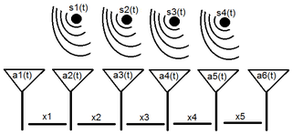
A sensor array is a group of sensors, usually deployed in a certain geometry pattern, used for collecting and processing electromagnetic or acoustic signals. The advantage of using a sensor array over using a single sensor lies in the fact that an array adds new dimensions to the observation, helping to estimate more parameters and improve the estimation performance. For example an array of radio antenna elements used for beamforming can increase antenna gain in the direction of the signal while decreasing the gain in other directions, i.e., increasing signal-to-noise ratio (SNR) by amplifying the signal coherently. Another example of sensor array application is to estimate the direction of arrival of impinging electromagnetic waves. The related processing method is called array signal processing. A third examples includes chemical sensor arrays, which utilize multiple chemical sensors for fingerprint detection in complex mixtures or sensing environments. Application examples of array signal processing include radar/sonar, wireless communications, seismology, machine condition monitoring, astronomical observations fault diagnosis, etc.
Array processing is a wide area of research in the field of signal processing that extends from the simplest form of 1 dimensional line arrays to 2 and 3 dimensional array geometries. Array structure can be defined as a set of sensors that are spatially separated, e.g. radio antenna and seismic arrays. The sensors used for a specific problem may vary widely, for example microphones, accelerometers and telescopes. However, many similarities exist, the most fundamental of which may be an assumption of wave propagation. Wave propagation means there is a systemic relationship between the signal received on spatially separated sensors. By creating a physical model of the wave propagation, or in machine learning applications a training data set, the relationships between the signals received on spatially separated sensors can be leveraged for many applications.
Beamforming or spatial filtering is a signal processing technique used in sensor arrays for directional signal transmission or reception. This is achieved by combining elements in an antenna array in such a way that signals at particular angles experience constructive interference while others experience destructive interference. Beamforming can be used at both the transmitting and receiving ends in order to achieve spatial selectivity. The improvement compared with omnidirectional reception/transmission is known as the directivity of the array.
In signal processing, direction of arrival (DOA) denotes the direction from which usually a propagating wave arrives at a point, where usually a set of sensors are located. These set of sensors forms what is called a sensor array. Often there is the associated technique of beamforming which is estimating the signal from a given direction. Various engineering problems addressed in the associated literature are:
An adaptive beamformer is a system that performs adaptive spatial signal processing with an array of transmitters or receivers. The signals are combined in a manner which increases the signal strength to/from a chosen direction. Signals to/from other directions are combined in a benign or destructive manner, resulting in degradation of the signal to/from the undesired direction. This technique is used in both radio frequency and acoustic arrays, and provides for directional sensitivity without physically moving an array of receivers or transmitters.

Space-time adaptive processing (STAP) is a signal processing technique most commonly used in radar systems. It involves adaptive array processing algorithms to aid in target detection. Radar signal processing benefits from STAP in areas where interference is a problem. Through careful application of STAP, it is possible to achieve order-of-magnitude sensitivity improvements in target detection.

In radio, multiple-input and multiple-output (MIMO) is a method for multiplying the capacity of a radio link using multiple transmission and receiving antennas to exploit multipath propagation. MIMO has become an essential element of wireless communication standards including IEEE 802.11n, IEEE 802.11ac, HSPA+ (3G), WiMAX, and Long Term Evolution (LTE). More recently, MIMO has been applied to power-line communication for three-wire installations as part of the ITU G.hn standard and of the HomePlug AV2 specification.
3G MIMO describes MIMO techniques which have been considered as 3G standard techniques.
CEA-909 is the ANSI standard for 8VSB/ATSC smart antennas. The basic concept is that the smart antenna either physically rotates toward the signal, or is stationary, but has elements pointed in different directions and uses only those elements that maximize the received signal. This is accomplished by feedback from the control device, such as a digital-to-analog converter box, telling the smart antenna when the signal is stronger or weaker.
Many antennas is a smart antenna technique which overcomes the performance limitation of single user multiple-input multiple-output (MIMO) techniques. In cellular communication, the maximum number of considered antennas for downlink is 2 and 4 to support 3GPP Long Term Evolution (LTE) and IMT Advanced requirements, respectively. Since the available spectrum band will probably be limited while the data rate requirement will continuously increase beyond IMT-A to support the mobile multimedia services, it is highly probable that the number of transmit antennas at the base station must be increased to 8–64 or more. The installation of many antennas at single base stations introduced many challenges and required development of several high technologies: a new SDMA engine, a new beamforming algorithm and a new antenna array.
WSDMA is a high bandwidth channel access method, developed for multi-transceiver systems such as active array antennas. WSDMA is a beamforming technique suitable for overlay on the latest air-interface protocols including WCDMA and OFDM. WSDMA enabled systems can determine the angle of arrival (AoA) of received signals to spatially divide a cell sector into many sub-sectors. This spatial awareness provides information necessary to maximise Carrier to Noise+Interference Ratio (CNIR) link budget, through a range of digital processing routines. WSDMA facilitates a flexible approach to how uplink and downlink beamforming is performed and is capable of spatial filtering known interference generating locations.

A plasma antenna is a type of radio antenna currently in development in which plasma is used instead of the metal elements of a traditional antenna. A plasma antenna can be used for both transmission and reception. Although plasma antennas have only become practical in recent years, the idea is not new; a patent for an antenna using the concept was granted to J. Hettinger in 1919.

An antenna array is a set of multiple connected antennas which work together as a single antenna, to transmit or receive radio waves. The individual antennas are usually connected to a single receiver or transmitter by feedlines that feed the power to the elements in a specific phase relationship. The radio waves radiated by each individual antenna combine and superpose, adding together to enhance the power radiated in desired directions, and cancelling to reduce the power radiated in other directions. Similarly, when used for receiving, the separate radio frequency currents from the individual antennas combine in the receiver with the correct phase relationship to enhance signals received from the desired directions and cancel signals from undesired directions. More sophisticated array antennas may have multiple transmitter or receiver modules, each connected to a separate antenna element or group of elements.
The first smart antennas were developed for military communications and intelligence gathering. The growth of cellular telephone in the 1980s attracted interest in commercial applications. The upgrade to digital radio technology in the mobile phone, indoor wireless network, and satellite broadcasting industries created new opportunities for smart antennas in the 1990s, culminating in the development of the MIMO technology used in 4G wireless networks.
A reconfigurable antenna is an antenna capable of modifying its frequency and radiation properties dynamically, in a controlled and reversible manner. In order to provide a dynamic response, reconfigurable antennas integrate an inner mechanism that enable the intentional redistribution of the RF currents over the antenna surface and produce reversible modifications of its properties. Reconfigurable antennas differ from smart antennas because the reconfiguration mechanism lies inside the antenna, rather than in an external beamforming network. The reconfiguration capability of reconfigurable antennas is used to maximize the antenna performance in a changing scenario or to satisfy changing operating requirements.
Three-dimensional beamforming (3DBF), full dimension MIMO or tilt angle adaptation is an interference coordination method in cellular networks and radar systems which brings significant improvements in comparison with conventional 2D beamforming techniques. Most beamforming schemes currently employed in wireless cellular networks control the beam pattern radiation in the horizontal plane. In contrast to such two-dimensional beamforming (2DBF), 3DBF adapts the radiation beam pattern in both elevation and azimuth planes to provide more degrees of freedom in supporting users. By utilizing information on angle of arrival (AoA) of users provided by suitable antenna hardware such as sector antenna or planar array in both elevation and azimuth planes and estimating direction of arrival (DoA) of each users' signal, base station is capable of distinguishing different users using proper beamforming and also steering the array's beam to a desired direction which optimizes some preferred performance metric of the network.

Digital antenna array(DAA) is a smart antenna with multi channels digital beamforming, usually by using fast Fourier transform (FFT). The development and practical realization of digital antenna arrays theory started in 1962 under the guidance of Vladimir Varyukhin (USSR).