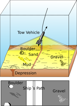
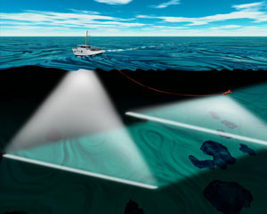
A multibeam echosounder (MBES) is a type of sonar that is used to map the seabed. It emits acoustic waves in a fan shape beneath its transceiver. The time it takes for the sound waves to reflect off the seabed and return to the receiver is used to calculate the water depth. Unlike other sonars and echo sounders, MBES uses beamforming to extract directional information from the returning soundwaves, producing a swathe of depth soundings from a single ping.
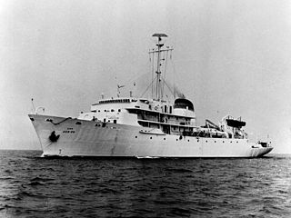
Multibeam sonar sounding systems, also known as swathe (British English) or swath (American English) [citation needed], originated for military applications. The concept originated in a radar system that was intended for the Lockheed U-2 high altitude reconnaissance aircraft, but the project was derailed when the aircraft flown by Gary Powers was brought down by a Soviet missile in May 1960. A proposal for using the "Mills Cross" beamforming technique adapted for use with bottom mapping sonar was made to the US Navy. Data from each ping of the sonar would be automatically processed, making corrections for ship motion and transducer depth sound velocity and refraction effects, but at the time there was insufficient digital data storage capacity, so the data would be converted into a depth contour strip map and stored on continuous film.[1] The Sonar Array Sounding System (SASS) was developed in the early 1960s by the US Navy, in conjunction with General Instrument to map large swathes of the ocean floor to assist the underwater navigation of its submarine force.[1][2] SASS was tested aboard the USS Compass Island (AG-153). The final array system, composed of sixty-one one degree beams with a swathe width of approximately 1.15 times water depth, was then installed on the USNS Bowditch (T-AGS-21), USNS Dutton (T-AGS-22) and USNS Michelson (T-AGS-23).[1]
At the same time, a Narrow Beam Echo Sounder (NBES) using 16 narrow beams was also developed by Harris ASW and installed on the Survey Ships Surveyor, Discoverer and Researcher. This technology would eventually become Sea Beam Only the vertical centre beam data was recorded during surveying operations.[1]
Starting in the 1970s, companies such as General Instrument (now SeaBeam Instruments, part of L3 Klein) in the United States, Krupp Atlas (now Atlas Hydrographic) and Elac Nautik (now part of the Wärtsilä Corporation) in Germany, Simrad (now Kongsberg Maritime) in Norway and RESON now Teledyne RESON A/S in Denmark developed systems that could be mounted to the hull of large ships, as well as on small boats (as technology improved, multibeam echosounders became more compact and lighter, and operating frequencies increased).
The first commercial multibeam is now known as the SeaBeam Classic and was put in service in May 1977[3] on the Australian survey vessel HMAS Cook. This system produced up to 16 beams across a 45-degree arc. The (retronym) term "SeaBeam Classic" was coined after the manufacturer developed newer systems such as the SeaBeam 2000 and the SeaBeam 2112 in the late 1980s.
The second SeaBeam Classic installation was on the French Research Vessel Jean Charcot. The SB Classic arrays on the Charcot were damaged in a grounding and the SeaBeam was replaced with an EM120 in 1991. Although it seems that the original SeaBeam Classic installation was not used much, the others were widely used, and subsequent installations were made on many vessels.
As technology improved in the 1980s and 1990s, higher-frequency systems which provided higher resolution mapping in shallow water were developed, and today such systems are widely used for shallow-water hydrographic surveying in support of navigational charting. Multibeam echosounders are also commonly used for geological and oceanographic research, and since the 1990s for offshore oil and gas exploration and seafloor cable routing. More recently, multibeam echsounders are also used in the renewable energy sector such as offshore windfarms.
In 1989, Atlas Electronics (Bremen, Germany) installed a second-generation deep-sea multibeam called Hydrosweep DS on the German research vessel Meteor. The Hydrosweep DS (HS-DS) produced up to 59 beams across a 90-degree swath, which was a vast improvement and was inherently ice-strengthened. Early HS-DS systems were installed on the RVMeteor (1986) (Germany), the RVPolarstern (Germany), the RVMaurice Ewing (US) and the ORVSagar Kanya (India) in 1989 and 1990 and subsequently on a number of other vessels including the RVThomas G. Thompson (US) and RVHakurei Maru (Japan).
As multibeam acoustic frequencies have increased and the cost of components has decreased, the worldwide number of multibeam swathe systems in operation has increased significantly. The required physical size of an acoustic transducer used to develop multiple high-resolution beams, decreases as the multibeam acoustic frequency increases. Consequently, increases in the operating frequencies of multibeam sonars have resulted in significant decreases in their weight, size and volume characteristics. The older and larger, lower-frequency multibeam sonar systems, that required considerable time and effort mounting them onto a ship's hull, used conventional tonpilz-type transducer elements, which provided a usable bandwidth of approximately 1/3 octave. The newer and smaller, higher-frequency multibeam sonar systems can easily be attached to a survey launch or to a tender vessel. Shallow water multibeam echosounders, like those from Teledyne Odom, R2Sonic and Norbit, which can incorporate sensors for measuring transducer motion and sound speed local to the transducer, are allowing many smaller hydrographic survey companies to move from traditional single beam echosounders to multibeam echosounders. Small low-power multibeam swathe systems are also now suitable for mounting on an Autonomous Underwater Vehicle (AUV) and on an Autonomous Surface Vessel (ASV).
Multibeam echosounder data may include bathymetry, acoustic backscatter, and water column data. (Gas plumes now commonly identified in midwater multibeam data are termed flares.)
Type 1-3 piezo-composite transducer elements, [4] are being employed in a multispectral multibeam echosounder to provide a usable bandwidth that is in excess of 3 octaves. Consequently, multispectral multibeam echosounder surveys are possible with a single sonar system, which during every ping cycle, collects multispectral bathymetry data, multispectral backscatter data, and multispectral water column data in each swathe. [5]
A multibeam echosounder showing the transmit array (larger black rectangle) and receive array (narrower rectangle) - Odom MB1
Theory of operation
A multibeam echosounder is a device typically used by hydrographic surveyors to determine the depth of water and the nature of the seabed. Most modern systems work by transmitting a broad acoustic fan shaped pulse from a specially designed transducer across the full swathe acrosstrack with a narrow alongtrack then forming multiple receive beams (beamforming) that are much narrower in the acrosstrack (around 1 degree depending on the system). From this narrow beam, a two way travel time of the acoustic pulse is then established utilizing a bottom detection algorithm. If the speed of sound in water is known for the full water column profile, the depth and position of the return signal can be determined from the receive angle and the two-way travel time.
In order to determine the transmit and receive angle of each beam, a multibeam echosounder requires accurate measurement of the motion of the sonar relative to a cartesian coordinate system. The measured values are typically heave, pitch, roll, yaw, and heading.
To compensate for signal loss due to spreading and absorption a time-varied gain circuit is designed into the receiver.
For deep water systems, a steerable transmit beam is required to compensate for pitch. This can also be accomplished with beamforming.
This section needs expansionwith: signal processing, corrections and data processing to produce graphic product. Point cloud, wire-frame model, isobath presentation, 2-D and 3-D models. You can help by adding to it. (January 2023)
Related Research Articles
The Challenger Deep is the deepest known point of the seabed of Earth. Its depth is measured at 10,902–10,929 m (35,768–35,856 ft) by direct measurement from deep-diving submersibles, remotely operated underwater vehicles and benthic landers, and (sometimes) slightly more by sonar bathymetry.
Sonar is a technique that uses sound propagation to navigate, measure distances (ranging), communicate with or detect objects on or under the surface of the water, such as other vessels.
Side-scan sonar is a category of sonar system that is used to efficiently create an image of large areas of the sea floor.
Echo sounding or depth sounding is the use of sonar for ranging, normally to determine the depth of water (bathymetry). It involves transmitting acoustic waves into water and recording the time interval between emission and return of a pulse; the resulting time of flight, along with knowledge of the speed of sound in water, allows determining the distance between sonar and target. This information is then typically used for navigation purposes or in order to obtain depths for charting purposes.
Hydrographic survey is the science of measurement and description of features which affect maritime navigation, marine construction, dredging, offshore oil exploration and drilling and related activities. Strong emphasis is placed on soundings, shorelines, tides, currents, seabed and submerged obstructions that relate to the previously mentioned activities. The term hydrography is used synonymously to describe maritime cartography, which in the final stages of the hydrographic process uses the raw data collected through hydrographic survey into information usable by the end user.
A bathymetric chart is a type of isarithmic map that depicts the submerged topography and physiographic features of ocean and sea bottoms. Their primary purpose is to provide detailed depth contours of ocean topography as well as provide the size, shape and distribution of underwater features. Topographic maps display elevation above ground and are complementary to bathymetric charts. Charts use a series of lines and points at equal intervals to showcase depth or elevation. A closed shape with increasingly smaller shapes inside of it can indicate an ocean trench or a seamount, or underwater mountain, depending on whether the depths increase or decrease going inward.
Bathymetry is the study of underwater depth of ocean floors, lake floors, or river floors. In other words, bathymetry is the underwater equivalent to hypsometry or topography. The first recorded evidence of water depth measurements are from Ancient Egypt over 3000 years ago. Bathymetric charts, are typically produced to support safety of surface or sub-surface navigation, and usually show seafloor relief or terrain as contour lines and selected depths (soundings), and typically also provide surface navigational information. Bathymetric maps may also use a Digital Terrain Model and artificial illumination techniques to illustrate the depths being portrayed. The global bathymetry is sometimes combined with topography data to yield a global relief model. Paleobathymetry is the study of past underwater depths.
Beamforming or spatial filtering is a signal processing technique used in sensor arrays for directional signal transmission or reception. This is achieved by combining elements in an antenna array in such a way that signals at particular angles experience constructive interference while others experience destructive interference. Beamforming can be used at both the transmitting and receiving ends in order to achieve spatial selectivity. The improvement compared with omnidirectional reception/transmission is known as the directivity of the array.
A scientific echosounder is a device which uses sonar technology for the calibrated backscatter measurement of underwater physical and biological components—this device is also known as scientific sonar. Applications include bathymetry, substrate classification, studies of aquatic vegetation, fish, and plankton, and differentation of water masses.
Sodar, an acronym of sonic detection and ranging, is a meteorological instrument used as a wind profiler based on the scattering of sound waves by atmospheric turbulence. Sodar equipment is used to measure wind speed at various heights above the ground, and the thermodynamic structure of the lower layer of the atmosphere.
USNS Pathfinder is a United States Navy oceanographic survey ship, and the lead vessel of her class. Her mission is to collect acoustical, biological, physical, and geophysical surveys of the world's oceans. This data has many uses, but a primary focus is characterizing the ocean environment in order to improve the U.S. Navy's undersea warfare capabilities.
NOAAS Thomas Jefferson is a National Oceanic and Atmospheric Administration (NOAA) hydrographic survey vessel in service since 2003. The ship was built for the United States Navy as USNS Littlehales (T-AGS-52) serving as one of two new coastal hydrographic survey vessels from 1992 until transfer to NOAA in 2003 when it was named after Founding Father and third U.S. president, Thomas Jefferson.
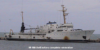
NOAAS Mount Mitchell was an American survey vessel in commission in the National Oceanic and Atmospheric Administration from 1970 to 1995. Prior to her NOAA career, she was in commission in the United States Coast and Geodetic Survey as USC&GS Mount Mitchell from 1968 to 1970. In 2003, she returned to service as the private research ship R/V Mt. Mitchell.
Acoustic seabed classification is the partitioning of a seabed acoustic image into discrete physical entities or classes. This is a particularly active area of development in the field of seabed mapping, marine geophysics, underwater acoustics and benthic habitat mapping. Seabed classification is one route to characterizing the seabed and its habitats. Seabed characterization makes the link between the classified regions and the seabed physical, geological, chemical or biological properties. Acoustic seabed classification is possible using a wide range of acoustic imaging systems including multibeam echosounders, sidescan sonar, single-beam echosounders, interferometric systems and sub-bottom profilers. Seabed classification based on acoustic properties can be divided into two main categories; surficial seabed classification and sub-surface seabed classification. Sub-surface imaging technologies use lower frequency sound to provide higher penetration, whereas surficial imaging technologies provide higher resolution imagery by utilizing higher frequencies.
USNS Silas Bent (T-AGS-26) was a Silas Bent class survey ship acquired by the United States Navy in 1964 and delivered to the Military Sealift Command in 1965. Silas Bent spent her career in the Pacific Ocean performing oceanographic surveys. The ship was equipped with the Oceanographic Data Acquisition System (ODAS) as were the later oceanographic survey ships USNS Kane(T-AGS-27) and USNS Wilkes(T-AGS-33).
Fisheries acoustics includes a range of research and practical application topics using acoustical devices as sensors in aquatic environments. Acoustical techniques can be applied to sensing aquatic animals, zooplankton, and physical and biological habitat characteristics.
A sound velocity probe is a device that is used for measuring the speed of sound, specifically in the water column, for oceanographic and hydrographic research purposes.
RESON A/S is a Danish company which provides tools for underwater acoustic applications and survey accuracy requirements.
The RV Denar 2 is a Turkish research and survey vessel owned by TOMA Maritime S.A. Istanbul, Turkey and operated 2E Maritime in Istanbul, Turkey.
An underwater survey is a survey performed in an underwater environment or conducted remotely on an underwater object or region. Survey can have several meanings. The word originates in Medieval Latin with meanings of looking over and detailed study of a subject. One meaning is the accurate measurement of a geographical region, usually with the intention of plotting the positions of features as a scale map of the region. This meaning is often used in scientific contexts, and also in civil engineering and mineral extraction. Another meaning, often used in a civil, structural, or marine engineering context, is the inspection of a structure or vessel to compare actual condition with the specified nominal condition, usually with the purpose of reporting on the actual condition and compliance with, or deviations from, the nominal condition, for quality control, damage assessment, valuation, insurance, maintenance, and similar purposes. In other contexts it can mean inspection of a region to establish presence and distribution of specified content, such as living organisms, either to establish a baseline, or to compare with a baseline.
↑ U.S. Naval Research Laboratory/Marine Physics Branch (Code 7420). "GOMaP GLOBAL OCEAN MAPPING PROJECT". U.S. Naval Research Laboratory. Archived from the original on 2 July 2014. Retrieved 30 June 2014.
↑ Uchino, K., (Editor), (2016), Advanced Piezoelectic materials: Science and Technology, 2nd Edition, ISBN9780081014851
↑ Brown, C. J., Brissette, M., and Gazzola, V., (2019), Multispectral multibeam echo sounder backscatter as a tool for improved seafloor characterization., Geosciences, 9(3).
This page is based on this Wikipedia article Text is available under the CC BY-SA 4.0 license; additional terms may apply. Images, videos and audio are available under their respective licenses.