Simple antennas
The category of simple antennas consists of dipoles, monopoles, and loop antennas, all of which can be made with a single section of wire (with some exceptions).[ citation needed ] Dipoles and monopoles called linear antennas (or straight wire antennas) since their radiating parts lie along a single straight line. On rare occasions they are called electric antennas since they engage with the electric part of RF radiation, in contrast to loops, which correspondingly are magnetic.
Dipoles
 "Rabbit ears" dipole variant for VHF television reception
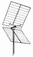
 Two-element turnstile antenna for reception of weather satellite data, 137 MHz. Has circular polarization.


The dipole consists of two conductors, usually metal rods or wires, usually arranged symmetrically, end-to-end, with one side of the balanced feedline from the transmitter or receiver attached to each, and usually elevated as high as feasible above the ground. [3] [lower-alpha 2] The most common type, the half-wave dipole, consists of two resonant elements just under a quarter wavelength long. This antenna radiates maximally in directions perpendicular to the antenna's axis, giving it a small directive gain of 2.15 dBi. Although half-wave dipoles are used alone as omnidirectional antennas, they are also a building block of many other more complicated directional antennas.
- Turnstile
- Two dipole antennas mounted at right angles, fed with a phase difference of 90°. This antenna is unusual in that it radiates in all directions (no nulls in the radiation pattern), with horizontal polarization in directions coplanar with the elements, circular polarization normal to that plane, and elliptical polarization in other directions. Used for receiving signals from satellites, as circular polarization is transmitted by many satellites.
- Patch (microstrip)
- A type of antenna with elements consisting of metal sheets mounted over a ground plane. Similar to dipole with gain of 6–9 dBi. Integrated into surfaces such as aircraft bodies. Their easy fabrication using PCB techniques have made them popular in modern wireless devices. Often combined into arrays.
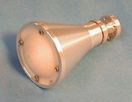
- Biconical antenna
- A dipole with cone-shaped arms, with the feedpoint where their tips meet. They show broader bandwidth than ordinary dipoles, up to three octaves above their base frequency.
- Bow-tie antenna
- Also called a butterfly antenna – a dipole whose arms are triangular or arrow-shaped (⧓ ⨝ ⪥) with the feedpoint where the tips of the triangles meet. It is a flattened version of a biconical antenna. The triangles can either be cut from sheet metal with solid metal centers (⧓), or two wires with their far ends connected (⨝) outlining the shape of a bow-tie, or with unconnected ends in an "X" shape (⪥). [lower-alpha 3]
- Fan dipole
- Also called a multi-dipole – a common broadband and / or wideband dipole variant that superficially resembles the bow-tie antenna, but is electrically different. It is a composite of pairs of dipole arms; both arms of one of the dipoles are equal-length, but each dipole pair is a different length from every other pair. The several dipole arms extend away ( ⚞⚟ ⪫⪪ ⫸⫷ ) from the common central connection point of the combined antenna. [lower-alpha 4]
Monopoles
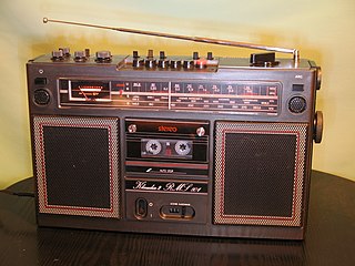 Quarter-wave whip antenna on an FM radio for 88–108 MHz
 VHF ground plane antenna
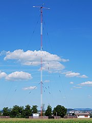 Mast radiator antenna of medium wave AM radio station, Germany
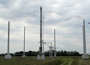
 Folded unipole antenna with a solid metal mast surrounded by six skirt wires, held away by insulated standoffs


A monopole antenna is a half-dipole (see above); it consists of a single conductor such as a metal rod, usually mounted over the ground or an artificial conducting surface (a so-called ground plane ). [3] [6] They are sometimes classed together with dipoles (see above) in the broader category of linear antennas, or more plainly straight wire antennas, since their radiating section is normally a straight (linear) wire or aluminum tubing; rarely, both dipoles and monopoles are called electric antennas, since they interact with the electric field of a radio wave, to contrast them against all sizes of loops, which are correspondingly magnetic antennas. [lower-alpha 5]
One side of the feedline from the receiver or transmitter is connected to the conductor, and the other side to ground or the artificial ground plane. The radio waves from the monopole reflected off the ground plane appear as if they came from a fictitious image antenna seemingly below the ground plane, with the monopole and its phantom image effectively forming a dipole. Hence, the monopole antenna has a radiation pattern identical to the top half of the pattern of a similar dipole antenna, and a radiation efficiency a bit less than half of the dipole. Since all of the equivalent dipole's radiation is concentrated in a half-space, the antenna has twice (3 dB increase of) the gain of a similar dipole, neglecting power lost in the ground plane.
The most common form is the quarter-wave monopole which is one-quarter of a wavelength long and has a gain of 5.12 dBi when mounted over a ground plane. Single monopoles have an omnidirectional radiation pattern, so they are used for broad coverage of an area, and have vertical polarization. To reduce signal absorption by the Earth, ground waves used for broadcasting at low frequencies must be vertically polarized, so large vertical monopole antennas are used for broadcasting in the MF, LF, and VLF bands. Small monopoles ("whips") are used as nondirectional antennas on portable radios in the HF, VHF, and UHF bands.
- Whip
- Type of antenna used on mobile and portable radios in the VHF and UHF bands such as FM "boom boxes", consists of a flexible rod, often made of telescoping segments. In the HF band, "whip" typically refers to an antenna that is too short to resonate naturally; when a whip is long enough to self-resonate (a quarter wavelength or more), it is instead usually just called by the generic name "monopole".
- "Rubber ducky"
- More formal technical name is normal-mode helix. Most common antenna used on portable two-way radios and cordless phones due to its compactness. Consists of an electrically short wire helix. The helical shape adds inductance to cancel the capacitive reactance of the short radiator, making it resonant. Like all electrically short antennas it is nearly isotropic – has very low gain. Not to be confused with the much larger axial mode helix (see below). [lower-alpha 6]
- Ground plane antenna
- A whip antenna with several rods extending horizontally from base of the whip, attached to the ground side of the feedline. Since the whip is mounted above ground, the horizontal rods form an elevated ground plane just below the whip to reflect its radiation away from the earth and increase its gain. Used for elevated base station antennas for land mobile radio systems such as police, ambulance, and taxi dispatchers.
- Mast radiator
- A radio tower in which the tower structure itself serves as the antenna. Common form of transmitting antenna for AM radio stations and other MF and LF transmitters. At its base the tower is usually, but not necessarily, mounted on a ceramic insulator to isolate it from the ground.
- Folded unipole antenna
- A modified mast antenna, usually grounded at its base, augmented by one or several parallel wires called "skirt wires" that attach to the mast part-way up the antenna. The skirt wires can attach at any height between part-way up and the top of the mast. One or more of the skirt wires is fed with the signal, similar to a gamma match. The number and relative thickness of the mast and the skirt wires adjusts the feedpoint impedance. [lower-alpha 7]
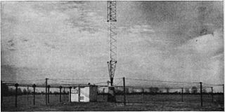
- 'T' antenna
- Consists of a long horizontal wire suspended between two towers with insulators, with a vertical wire hanging down from it, attached to a feedline to the receiver or transmitter on one feed wire and the other to a required low resistance ground. The dangling vertical wire is the radiating part of the antenna; normally it is shorter than the quarter wavelength required for resonance. For the 'T' antenna, the dangling wire attaches in the exact center of the top wire. Used on MF and the lower HF bands. Since at these frequencies the vertical wire is electrically short – much shorter than a quarter wavelength – the horizontal wire serves as a "capacitance hat" to increase the current in the vertical radiator, increasing the efficiency and gain. Since equal horizontal currents travel in opposite directions away from the center of the top wire, those currents balance and produce essentially no radiation. Usually the horizontal section is not long enough to supply sufficient capacitance, so the antenna feedpoint requires a loading coil to tune out any remaining reactance, and the tuned antenna will have narrow bandwidth. When the "capacitance hat" is wide enough to compensate for the missing length on the vertical wire, a 'T' antenna's performance can come close to a full-size monopole.
- Inverted 'L'
- Similar in construction to a 'T' antenna described above, but with the dangling vertical wire attached to one end of the horizontal wire instead of the center. The altered connection point gives the antenna the shape of the Greek letter Γ. Unlike the 'T' antenna, both the vertical and horizontal wires radiate, with their respective radiation being vertically and horizontally polarized, and their combined radiation diagonally polarized, usually at a steep angle. Although all parts of the antenna radiate, the strongest radiation comes from the vertical wire, so the horizontal wire serves both as a "capacitance hat" and as a weak radiator. If the length of the horizontal wire is sufficient to make the total length of wire about a quarter wavelength, the inverted-L's performance can come close to a full-size monopole.
- Inverted 'F'
- Combines the advantages of the compactness of inverted-L antenna, and the good matching of the unipole antenna. The antenna is grounded at the base and fed at some intermediate point. The position of the feed point determines the antenna impedance. Thus, matching can be achieved without the need for a separate matching network. Effectively a shunt-fed inverted-L, with the feed point attached to the horizontal wire rather than the vertical, giving the antenna the shape of the line-drawing character ╓, or the Hangul letter ㄲ.
- Umbrella
- An elaborated and enlarged version of a 'T' antenna; it is a very large wire transmitting antenna with extremely narrow bandwidth, used on VLF bands for VLF time signals or long-range submarine communications. Relative to the even larger wavelengths it is used for, it is paradoxically an ultra-short antenna. It consists of a central radiating tower with multiple wires attached at the top, extending out radially from the mast and insulated at the ends, resembling a metal umbrella frame. Like other ultra-short antennas it has an extremely high capacitive reactance and minimal radiation resistance, which require a large loading coil and low-resistance counterpoise system.
Loop antennas


Loop antennas consist of a loop (or coil) of wire. Loop antennas interact directly with the magnetic field of the radio wave, rather than its electric field as linear antennas do; for that reason they are on rare occasions categorized as magnetic antennas, but that generic name is confusingly similar to the term magnetic loop used to describe small loops. [lower-alpha 5] Their exclusive interaction with the magnetic field makes them relatively insensitive to electrical spark noise within about 1/ 6 wavelength of the antenna, [3] [7] [2] and more tolerant of being mounted close to the ground, since for most soils the earth is closer to being somewhat radio-transparent to the magnetic part of mediumwaves and longer shortwaves, than is the case for their electric part. There are essentially two broad categories of loop antennas: large loops (or full-wave loops) and small loops. Only one design, a halo antenna, that is normally called a loop does not clearly fit exclusively into either the large or small loop categories.
Large loops
Full-wave loops have the highest radiation resistance, and hence the highest efficiency of all antennas: Their radiation resistances are several hundreds of Ohms, whereas dipoles and monopoles are tens of Ohms, and small loops and short whip antennas are a few ohms, or even fractions of an Ohm. [2]
- Large loops
- Large loops have a perimeter of one full wavelength, or larger. When they are one, two, or three wavelengths, or any whole-number multiple of a wavelength, they are naturally resonant and act somewhat similarly to the full-wave or multi-wave dipole. When it is necessary to distinguish them from small loops, they are called "full-wave" loops. [lower-alpha 8] [3] [7]
- Half-loop
- the upper half of a vertical full-wavelength loop antenna mounted on the ground (not to be confused with the somewhat similar half-square antenna described above). [lower-alpha 9] The full loop is cut at two opposite points along its perimeter, and the lower half is omitted; the upper half mounted on the ground at the cut points, sticking up from the ground like a satchel handle. It is shaped like the Greek letter Π or an upside-down capital letter U, and is the loop antenna analog of a ground-mounted monopole antenna. Like a vertical monopole, the missing lower half of the antenna is replaced by its ground-plane image. If shaped like a half of a square, a half-loop can operate either as a loop antenna or on its first harmonic, depending on the position of its feed-point, as a dipole antenna whose ends have been bent over and grounded. [8]
Halo antennas: Unique in-between loops
- Halo antennas
- Loops one half-wavelength in perimeter, that have a small gap cut in the loop, are called "halos". They are naturally resonant on one frequency, and are intermediate in size and function between small and large loops. They are often described as a half-wavelength dipole that has been folded into a circle, rather than being a "true loop" antenna. [3] [7] [2] [4] (pp231–275)
The approximately-omnidirectional pattern of halos resembles small loops; their radiation efficiency lies inbetween the extreme high efficiency of large loops and the generally poor efficiency of small loops. Halos are self-resonant like full-wave loops, but have no useable higher harmonics. In some regards they represent the extreme upper size limit of small transmitting loops. [3] [2] [4] (pp231–275)
Small loops
Small loop antennas have very low radiation resistance – typically much smaller than the loss resistance of the wire they are made of, making them inefficient for transmitting. Their directionality and low radiation efficiency is drastically different from full-wave loops, and if the loop perimeter is smaller than a half-wavelength, if resonance is necessary the loop must be modified in some way to make it resonant. Despite their drawbacks, small loops are widely used as receiving antennas, especially at lower frequencies, where their inefficiency is not an issue and their small size makes them a useful solution to the excessive sizes even of quarter-wave antennas. The fact that they can be efficiently tuned to accept only a very narrow frequency range (similar to a preselector) helps alleviate much of the trouble caused by the pervasive static always encountered on the mediumwaves and lower shortwaves. Small loops are called "magnetic loops"; they are also called "tuned loops" since small loops typically must be modified by adding capacitance to make them resonate on some frequency lower than any that they would "naturally" resonate on.
- Small receiving loops
- Small receiving loops are sized at 1 /4~1/ 10 wave perimeters, sometimes with many turns of wire around the same supporting frame. Small loops are widely used as compact direction finding antennas, since their "null" direction is exceptionally precise, and their small size makes them much more compact as hand-carried equipment than dipole-based directional antennas. [3] [7] [2]
- Ferrite loop antennas
- Also called "loopsticks", they consist of a wire coiled around a cylindrical ferrite core (the "stick"). The ferrite increases the coil's inductance hundreds to thousands of times larger, and likewise magnifies its effective signal-capturing area. The improvement makes them even more compact than (ordinary) small loops made without ferrite, and yet receive RF just as well (or better). Loopsticks' radiation pattern is identical to a dipole antenna, with a maximum in all directions perpendicular to the ferrite rod. These are used as the receiving antenna in most portable and desktop consumer AM radios made for the medium wave broadcast band, and for lower frequencies. [lower-alpha 10]
- Small transmitting loops
- Small transmitting loops are loop antennas whose perimeters are smaller than a half-wave, that have been specifically optimized for transmitting. Their much smaller size than dipole antennas (only ~10% as wide) sometimes makes them a viable choice, despite their lower efficiency. Small transmitting loops are made larger in size than most small receiving loops, with perimeters near 1 /3~ 1 /4 wave, [lower-alpha 11] in order to improve on their generally poor efficiency. For that same reason, their parts are carefully joined by brazing or welding to reduce losses from contact resistance. Because of their larger size, small transmitting loops lack the sharp nulls of small receiving loops, so they are not as useful for direction finding, and also are more bulky (roughly double the size) so would not be as convenient as the more accurate small loops for hand-held use in radio searches. [2]
The nulls in the radiation pattern of small receiving loops and ferrite core antennas are bi-directional, and are much sharper than the directions of maximum power of either loop or of linear antennas, and even most beam antennas; the null directionality of small loops is comparable to the maximal directionality of large dish antennas (aperture antennas, see below).[ citation needed ] For accurately locating a signal source, this makes the small receiving loop's null direction much more precise than the direction of the strongest signal, and the small loop / ferrite core type antennas are widely used for radio direction finding (RDF). The null direction of small loops can also be exploited to exclude unwanted signals from an interfering station or noise source. [3] [7] [2] Several construction techniques are used to ensure that small receiving loops' null directions are "sharp", including making the perimeter 1/ 10 wavelength, (or at most 1 /4 wavelength). Small transmitting loops' perimeters are instead made as large as feasibly possible, up to 1 /3 wave, or even 1 /2, if possible, in order to improve their generally poor efficiency; however, doing so blurs or erases small transmitting loops' directional nulls.