
In mathematical physics and mathematics, the Pauli matrices are a set of three 2 × 2 complex matrices which are Hermitian, involutory and unitary. Usually indicated by the Greek letter sigma, they are occasionally denoted by tau when used in connection with isospin symmetries.
The propagation constant of a sinusoidal electromagnetic wave is a measure of the change undergone by the amplitude and phase of the wave as it propagates in a given direction. The quantity being measured can be the voltage, the current in a circuit, or a field vector such as electric field strength or flux density. The propagation constant itself measures the change per unit length, but it is otherwise dimensionless. In the context of two-port networks and their cascades, propagation constant measures the change undergone by the source quantity as it propagates from one port to the next.

A gyrocompass is a type of non-magnetic compass which is based on a fast-spinning disc and the rotation of the Earth to find geographical direction automatically. The use of a gyrocompass is one of the seven fundamental ways to determine the heading of a vehicle. A gyroscope is an essential component of a gyrocompass, but they are different devices; a gyrocompass is built to use the effect of gyroscopic precession, which is a distinctive aspect of the general gyroscopic effect. Gyrocompasses are widely used for navigation on ships, because they have two significant advantages over magnetic compasses:

Johnson–Nyquist noise is the electronic noise generated by the thermal agitation of the charge carriers inside an electrical conductor at equilibrium, which happens regardless of any applied voltage. Thermal noise is present in all electrical circuits, and in sensitive electronic equipment can drown out weak signals, and can be the limiting factor on sensitivity of electrical measuring instruments. Thermal noise increases with temperature. Some sensitive electronic equipment such as radio telescope receivers are cooled to cryogenic temperatures to reduce thermal noise in their circuits. The generic, statistical physical derivation of this noise is called the fluctuation-dissipation theorem, where generalized impedance or generalized susceptibility is used to characterize the medium.
In mathematics, a Gaussian function, often simply referred to as a Gaussian, is a function of the base form
In physics, the S-matrix or scattering matrix relates the initial state and the final state of a physical system undergoing a scattering process. It is used in quantum mechanics, scattering theory and quantum field theory (QFT).
In electrical engineering and electronics, a network is a collection of interconnected components. Network analysis is the process of finding the voltages across, and the currents through, all network components. There are many techniques for calculating these values; however, for the most part, the techniques assume linear components. Except where stated, the methods described in this article are applicable only to linear network analysis.
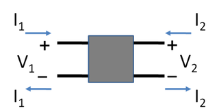
In electronics, a two-port network is an electrical network or device with two pairs of terminals to connect to external circuits. Two terminals constitute a port if the currents applied to them satisfy the essential requirement known as the port condition: the current entering one terminal must equal the current emerging from the other terminal on the same port. The ports constitute interfaces where the network connects to other networks, the points where signals are applied or outputs are taken. In a two-port network, often port 1 is considered the input port and port 2 is considered the output port.
Scattering parameters or S-parameters describe the electrical behavior of linear electrical networks when undergoing various steady state stimuli by electrical signals.
In power engineering, nodal admittance matrix or Y Matrix or Ybus is an N x N matrix describing a linear power system with N buses. It represents the nodal admittance of the buses in a power system. In realistic systems which contain thousands of buses, the Y matrix is quite sparse. Each bus in a real power system is usually connected to only a few other buses through the transmission lines. The Y Matrix is also one of the data requirements needed to formulate a power-flow study.

An attenuator is an electronic device that reduces the power of a signal without appreciably distorting its waveform.
In statistics, the multivariate t-distribution is a multivariate probability distribution. It is a generalization to random vectors of the Student's t-distribution, which is a distribution applicable to univariate random variables. While the case of a random matrix could be treated within this structure, the matrix t-distribution is distinct and makes particular use of the matrix structure.
Impedance parameters or Z-parameters are properties used in electrical engineering, electronic engineering, and communication systems engineering to describe the electrical behavior of linear electrical networks. They are also used to describe the small-signal (linearized) response of non-linear networks. They are members of a family of similar parameters used in electronic engineering, other examples being: S-parameters, Y-parameters, H-parameters, T-parameters or ABCD-parameters.

The Π pad is a specific type of attenuator circuit in electronics whereby the topology of the circuit is formed in the shape of the Greek capital letter pi (Π).
Image impedance is a concept used in electronic network design and analysis and most especially in filter design. The term image impedance applies to the impedance seen looking into a port of a network. Usually a two-port network is implied but the concept can be extended to networks with more than two ports. The definition of image impedance for a two-port network is the impedance, Zi 1, seen looking into port 1 when port 2 is terminated with the image impedance, Zi 2, for port 2. In general, the image impedances of ports 1 and 2 will not be equal unless the network is symmetrical with respect to the ports.
The transmission-line matrix (TLM) method is a space and time discretising method for computation of electromagnetic fields. It is based on the analogy between the electromagnetic field and a mesh of transmission lines. The TLM method allows the computation of complex three-dimensional electromagnetic structures and has proven to be one of the most powerful time-domain methods along with the finite difference time domain (FDTD) method.
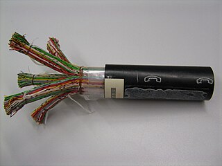
The primary line constants are parameters that describe the characteristics of conductive transmission lines, such as pairs of copper wires, in terms of the physical electrical properties of the line. The primary line constants are only relevant to transmission lines and are to be contrasted with the secondary line constants, which can be derived from them, and are more generally applicable. The secondary line constants can be used, for instance, to compare the characteristics of a waveguide to a copper line, whereas the primary constants have no meaning for a waveguide.
In control system theory, and various branches of engineering, a transfer function matrix, or just transfer matrix is a generalisation of the transfer functions of single-input single-output (SISO) systems to multiple-input and multiple-output (MIMO) systems. The matrix relates the outputs of the system to its inputs. It is a particularly useful construction for linear time-invariant (LTI) systems because it can be expressed in terms of the s-plane.
Performance modelling is the abstraction of a real system into a simplified representation to enable the prediction of performance. The creation of a model can provide insight into how a proposed or actual system will or does work. This can, however, point towards different things to people belonging to different fields of work.
Reciprocity in electrical networks is a property of a circuit that relates voltages and currents at two points. The reciprocity theorem states that the current at one point in a circuit due to a voltage at a second point is the same as the current at the second point due to the same voltage at the first. The reciprocity theorem is valid for almost all passive networks. The reciprocity theorem is a feature of a more general principle of reciprocity in electromagnetism.


