Anisotropic filtering

Last updated
An illustration of texture filtering methods showing a texture with trilinear mipmapping (left) and anisotropic texture filtering Anisotropic filtering en.png
An illustration of texture filtering methods showing a texture with trilinear mipmapping (left) and anisotropic texture filtering

In 3D computer graphics, anisotropic filtering (abbreviated AF) [1] [2] is a method of enhancing the image quality of textures on surfaces of computer graphics that are at oblique viewing angles with respect to the camera where the projection of the texture (not the polygon or other primitive on which it is rendered) appears to be non-orthogonal (thus the origin of the word: "an" for not, "iso" for same, and "tropic" from tropism, relating to direction; anisotropic filtering does not filter the same in every direction).

Contents

Like bilinear and trilinear filtering, anisotropic filtering eliminates aliasing effects, [3] [4] but improves on these other techniques by reducing blur and preserving detail at extreme viewing angles.

Anisotropic filtering is relatively intensive (primarily memory bandwidth and to some degree computationally, though the standard space–time tradeoff rules apply) and only became a standard feature of consumer-level graphics cards in the late 1990s. [5] Anisotropic filtering is now common in modern graphics hardware (and video driver software) and is enabled either by users through driver settings or by graphics applications and video games through programming interfaces.

An improvement on isotropic MIP mapping

An example of anisotropic mipmap image storage: the principal image on the top left is accompanied by filtered, linearly transformed copies of reduced size. MipMap Example STS101 Anisotropic.png
An example of anisotropic mipmap image storage: the principal image on the top left is accompanied by filtered, linearly transformed copies of reduced size.
Isotropic mipmap of the same image MipMap Example STS101.jpg
Isotropic mipmap of the same image

From this point forth, it is assumed the reader is familiar with MIP mapping.

If we were to explore a more approximate anisotropic algorithm, RIP mapping, as an extension from MIP mapping, we can understand how anisotropic filtering gains so much texture mapping quality. [6] If we need to texture a horizontal plane which is at an oblique angle to the camera, traditional MIP map minification would give us insufficient horizontal resolution due to the reduction of image frequency in the vertical axis. This is because in MIP mapping each MIP level is isotropic, so a 256 × 256 texture is downsized to a 128 × 128 image, then a 64 × 64 image and so on, so resolution halves on each axis simultaneously, so a MIP map texture probe to an image will always sample an image that is of equal frequency in each axis. Thus, when sampling to avoid aliasing on a high-frequency axis, the other texture axes will be similarly downsampled and therefore potentially blurred.

With MIP map anisotropic filtering, in addition to downsampling to 128 × 128, images are also sampled to 256 × 128 and 32 × 128 etc. These anisotropically downsampled images can be probed when the texture-mapped image frequency is different for each texture axis. Therefore, one axis need not blur due to the screen frequency of another axis, and aliasing is still avoided. Unlike more general anisotropic filtering, the MIP mapping described for illustration is limited by only supporting anisotropic probes that are axis-aligned in texture space, so diagonal anisotropy still presents a problem, even though real-use cases of anisotropic texture commonly have such screenspace mappings.

Although implementations are free to vary their methods, MIP mapping and the associated axis aligned constraints mean it is suboptimal for true anisotropic filtering and is used here for illustrative purposes only. Fully anisotropic implementation is described below.

In layman's terms, anisotropic filtering retains the "sharpness" of a texture normally lost by MIP map texture's attempts to avoid aliasing. Anisotropic filtering can therefore be said to maintain crisp texture detail at all viewing orientations while providing fast anti-aliased texture filtering.

Degree of anisotropy supported

Different degrees or ratios of anisotropic filtering can be applied during rendering and current hardware rendering implementations set an upper bound on this ratio. [7] This degree refers to the maximum ratio of anisotropy supported by the filtering process. For example, 4:1 (pronounced “4-to-1”) anisotropic filtering will continue to sharpen more oblique textures beyond the range sharpened by 2:1. [8]

In practice what this means is that in highly oblique texturing situations a 4:1 filter will be twice as sharp as a 2:1 filter (it will display frequencies double that of the 2:1 filter). However, most of the scene will not require the 4:1 filter; only the more oblique and usually more distant pixels will require the sharper filtering. This means that as the degree of anisotropic filtering continues to double there are diminishing returns in terms of visible quality with fewer and fewer rendered pixels affected, and the results become less obvious to the viewer.

When one compares the rendered results of an 8:1 anisotropically filtered scene to a 16:1 filtered scene, only a relatively few highly oblique pixels, mostly on more distant geometry, will display visibly sharper textures in the scene with the higher degree of anisotropic filtering, and the frequency information on these few 16:1 filtered pixels will only be double that of the 8:1 filter. The performance penalty also diminishes because fewer pixels require the data fetches of greater anisotropy.

In the end it is the additional hardware complexity vs. these diminishing returns, which causes an upper bound to be set on the anisotropic quality in a hardware design. Applications and users are then free to adjust this trade-off through driver and software settings up to this threshold.

Implementation

True anisotropic filtering probes the texture anisotropically on the fly on a per-pixel basis for any orientation of anisotropy.

In graphics hardware, typically when the texture is sampled anisotropically, several probes (texel samples) of the texture around the center point are taken, but on a sample pattern mapped according to the projected shape of the texture at that pixel, [9] although earlier software methods have used summed-area tables. [10]

Each anisotropic filtering probe is often in itself a filtered MIP map sample, which adds more sampling to the process. Sixteen trilinear anisotropic samples might require 128 samples from the stored texture, as trilinear MIP map filtering needs to take four samples times two MIP levels and then anisotropic sampling (at 16-tap) needs to take sixteen of these trilinear filtered probes.

However, this level of filtering complexity is not required all the time. There are commonly available methods to reduce the amount of work the video rendering hardware must do.

The anisotropic filtering method most commonly implemented on graphics hardware is the composition of the filtered pixel values from only one line of MIP map samples. In general the method of building a texture filter result from multiple probes filling a projected pixel sampling into texture space is referred to as "footprint assembly", even where implementation details vary. [11] [12] [13]

Performance and optimization

The sample count required can make anisotropic filtering extremely bandwidth-intensive. Multiple textures are common; each texture sample could be four bytes or more, so each anisotropic pixel could require 512 bytes from texture memory, although texture compression is commonly used to reduce this.

A video display device can easily contain over two million pixels, and desired application framerates are often upwards of 60 frames per second. As a result, the required texture memory bandwidth may grow to large values. Ranges of hundreds of gigabytes per second of pipeline bandwidth for texture rendering operations is not unusual where anisotropic filtering operations are involved. [14]

Fortunately, several factors mitigate in favor of better performance:

See also

Related Research Articles

<span class="mw-page-title-main">Rendering (computer graphics)</span> Process of generating an image from a model

Rendering or image synthesis is the process of generating a photorealistic or non-photorealistic image from a 2D or 3D model by means of a computer program. The resulting image is referred to as the render. Multiple models can be defined in a scene file containing objects in a strictly defined language or data structure. The scene file contains geometry, viewpoint, texture, lighting, and shading information describing the virtual scene. The data contained in the scene file is then passed to a rendering program to be processed and output to a digital image or raster graphics image file. The term "rendering" is analogous to the concept of an artist's impression of a scene. The term "rendering" is also used to describe the process of calculating effects in a video editing program to produce the final video output.

In digital signal processing, spatial anti-aliasing is a technique for minimizing the distortion artifacts (aliasing) when representing a high-resolution image at a lower resolution. Anti-aliasing is used in digital photography, computer graphics, digital audio, and many other applications.

<span class="mw-page-title-main">Texture mapping</span> Method of defining surface detail on a computer-generated graphic or 3D model

Texture mapping is a method for mapping a texture on a computer-generated graphic. Texture here can be high frequency detail, surface texture, or color.

<span class="mw-page-title-main">GeForce 3 series</span> Series of GPUs by Nvidia

The GeForce 3 series (NV20) is the third generation of Nvidia's GeForce graphics processing units (GPUs). Introduced in February 2001, it advanced the GeForce architecture by adding programmable pixel and vertex shaders, multisample anti-aliasing and improved the overall efficiency of the rendering process.

In computer graphics, mipmaps or pyramids are pre-calculated, optimized sequences of images, each of which is a progressively lower resolution representation of the previous. The height and width of each image, or level, in the mipmap is a factor of two smaller than the previous level. Mipmaps do not have to be square. They are intended to increase rendering speed and reduce aliasing artifacts. A high-resolution mipmap image is used for high-density samples, such as for objects close to the camera; lower-resolution images are used as the object appears farther away. This is a more efficient way of downfiltering (minifying) a texture than sampling all texels in the original texture that would contribute to a screen pixel; it is faster to take a constant number of samples from the appropriately downfiltered textures. Mipmaps are widely used in 3D computer games, flight simulators, other 3D imaging systems for texture filtering, and 2D and 3D GIS software. Their use is known as mipmapping. The letters MIP in the name are an acronym of the Latin phrase multum in parvo, meaning "much in little".

<span class="mw-page-title-main">Volume rendering</span> Representing a 3D-modeled object or dataset as a 2D projection

In scientific visualization and computer graphics, volume rendering is a set of techniques used to display a 2D projection of a 3D discretely sampled data set, typically a 3D scalar field.

In computer graphics, texture filtering or texture smoothing is the method used to determine the texture color for a texture mapped pixel, using the colors of nearby texels. There are two main categories of texture filtering, magnification filtering and minification filtering. Depending on the situation texture filtering is either a type of reconstruction filter where sparse data is interpolated to fill gaps (magnification), or a type of anti-aliasing (AA), where texture samples exist at a higher frequency than required for the sample frequency needed for texture fill (minification). Put simply, filtering describes how a texture is applied at many different shapes, size, angles and scales. Depending on the chosen filter algorithm the result will show varying degrees of blurriness, detail, spatial aliasing, temporal aliasing and blocking. Depending on the circumstances filtering can be performed in software or in hardware for real time or GPU accelerated rendering or in a mixture of both. For most common interactive graphical applications modern texture filtering is performed by dedicated hardware which optimizes memory access through memory cacheing and pre-fetch and implements a selection of algorithms available to the user and developer.

<span class="mw-page-title-main">SGI O2</span> Unix workstation from Silicon Graphics

The O2 was an entry-level Unix workstation introduced in 1996 by Silicon Graphics, Inc. (SGI) to replace their earlier Indy series. Like the Indy, the O2 used a single MIPS microprocessor and was intended to be used mainly for multimedia. Its larger counterpart was the SGI Octane. The O2 was SGI's last attempt at a low-end workstation.

Cone tracing and beam tracing are a derivative of the ray tracing algorithm that replaces rays, which have no thickness, with thick rays.

In computer graphics, per-pixel lighting refers to any technique for lighting an image or scene that calculates illumination for each pixel on a rendered image. This is in contrast to other popular methods of lighting such as vertex lighting, which calculates illumination at each vertex of a 3D model and then interpolates the resulting values over the model's faces to calculate the final per-pixel color values.

<span class="mw-page-title-main">Xenos (graphics chip)</span> GPU used in the Xbox 360

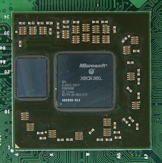
The Xenos is a custom graphics processing unit (GPU) designed by ATI, used in the Xbox 360 video game console developed and produced for Microsoft. Developed under the codename "C1", it is in many ways related to the R520 architecture and therefore very similar to an ATI Radeon X1800 XT series of PC graphics cards as far as features and performance are concerned. However, the Xenos introduced new design ideas that were later adopted in the TeraScale microarchitecture, such as the unified shader architecture. The package contains two separate dies, the GPU and an eDRAM, featuring a total of 337 million transistors.

In computer graphics, a texture mapping unit (TMU) is a component in modern graphics processing units (GPUs). They are able to rotate, resize, and distort a bitmap image to be placed onto an arbitrary plane of a given 3D model as a texture, in a process called texture mapping. In modern graphics cards it is implemented as a discrete stage in a graphics pipeline, whereas when first introduced it was implemented as a separate processor, e.g. as seen on the Voodoo2 graphics card.

<span class="mw-page-title-main">Supersampling</span> Spatial anti-aliasing method

Supersampling or supersampling anti-aliasing (SSAA) is a spatial anti-aliasing method, i.e. a method used to remove aliasing from images rendered in computer games or other computer programs that generate imagery. Aliasing occurs because unlike real-world objects, which have continuous smooth curves and lines, a computer screen shows the viewer a large number of small squares. These pixels all have the same size, and each one has a single color. A line can only be shown as a collection of pixels, and therefore appears jagged unless it is perfectly horizontal or vertical. The aim of supersampling is to reduce this effect. Color samples are taken at several instances inside the pixel, and an average color value is calculated. This is achieved by rendering the image at a much higher resolution than the one being displayed, then shrinking it to the desired size, using the extra pixels for calculation. The result is a downsampled image with smoother transitions from one line of pixels to another along the edges of objects. The number of samples determines the quality of the output.

<span class="mw-page-title-main">Texture compression</span>

Texture compression is a specialized form of image compression designed for storing texture maps in 3D computer graphics rendering systems. Unlike conventional image compression algorithms, texture compression algorithms are optimized for random access.

Talisman was a Microsoft project to build a new 3D graphics architecture based on quickly compositing 2D "sub-images" onto the screen, an adaptation of tiled rendering. In theory, this approach would dramatically reduce the amount of memory bandwidth required for 3D games and thereby lead to lower-cost graphics accelerators. The project took place during the introduction of the first high-performance 3D accelerators, and these quickly surpassed Talisman in both performance and price. No Talisman-based systems were ever released commercially, and the project was eventually cancelled in the late 1990s.

<span class="mw-page-title-main">InfiniteReality</span> Graphics subsystem by Silicon Graphics

InfiniteReality refers to a 3D graphics hardware architecture and a family of graphics systems that implemented the aforementioned hardware architecture that was developed and manufactured by Silicon Graphics from 1996 to 2005. The InfiniteReality was positioned as Silicon Graphics' high-end visualization hardware for their MIPS/IRIX platform and was used exclusively in their Onyx family of visualization systems, which are sometimes referred to as "graphics supercomputers" or "visualization supercomputers". The InfiniteReality was marketed to and used by large organizations such as companies and universities that are involved in computer simulation, digital content creation, engineering and research.

PICA200 is a graphics processing unit (GPU) designed by Digital Media Professionals Inc. (DMP), a Japanese GPU design startup company, for use in embedded devices such as vehicle systems, mobile phones, cameras, and game consoles. The PICA200 is an IP Core which can be licensed to other companies to incorporate into their SOCs. It was most notably licensed for use in the Nintendo 3DS.

<span class="mw-page-title-main">PlayStation 2 technical specifications</span> Overview of the PlayStation 2 technical specifications

The PlayStation 2 technical specifications describe the various components of the PlayStation 2 (PS2) video game console.

<span class="mw-page-title-main">Xbox technical specifications</span>

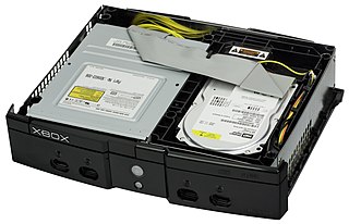
The Xbox technical specifications describe the various components of the Xbox video game console.

This is a glossary of terms relating to computer graphics.

References

  1. "What is Anisotropic Filtering? - Technipages". 8 July 2020.
  2. Ewins, Jon P.; Waller, Marcus D.; White, Martin; Lister, Paul F. (April 2000). "Implementing an anisotropic texture filter - ScienceDirect". Computers & Graphics. 24 (2): 253–267. doi:10.1016/S0097-8493(99)00159-4.
  3. Blinn, James F.; Newell, Martin E. (October 1976). "Graphics and Image Processing: Texture and Reflection in Computer Generated Images" (PDF). Communications of the ACM . 19 (10): 542–547. doi:10.1145/360349.360353. S2CID   408793 . Retrieved 2017-10-20.
  4. Heckbert, Paul S. (November 1986). "Survey Of Texture Mapping" (PDF). IEEE Computer Graphics and Applications . 6 (11): 56–67. doi:10.1109/MCG.1986.276672. S2CID   6398235 . Retrieved 2017-10-20.
  5. "Radeon Whitepaper" (PDF). ATI Technologies Inc. 2000. p. 23. Retrieved 2017-10-20.
  6. "Chapter 5: Texturing" (PDF). CS559, Fall 2003. University of Wisconsin–Madison. 2003. Retrieved 2017-10-20.
  7. "Anisotropic Filtering". Nvidia Corporation . Retrieved 2017-10-20.
  8. 1 2 3 "Texture antialiasing". ATI's Radeon 9700 Pro graphics card. The Tech Report. 16 September 2002. Retrieved 2017-10-20.
  9. Olano, Marc; Mukherjee, Shrijeet; Dorbie, Angus (2001). "Vertex-based anisotropic texturing". Proceedings of the ACM SIGGRAPH/EUROGRAPHICS workshop on Graphics hardware (PDF). pp. 95–98. CiteSeerX   10.1.1.1.6886 . doi:10.1145/383507.383532. ISBN   978-1581134070. S2CID   14022450. Archived from the original (PDF) on 2017-02-14. Retrieved 2017-10-20.
  10. Crow, Franklin C. (July 1984). "Summed-area tables for texture mapping". Proceedings of the 11th annual conference on Computer graphics and interactive techniques - SIGGRAPH '84 (PDF). pp. 207–212. doi:10.1145/800031.808600. ISBN   0897911385. S2CID   2210332 . Retrieved 2017-10-20.{{cite book}}: |journal= ignored (help)
  11. Schilling, A.; Knittel, G.; Strasser, W. (May 1996). "Texram: a smart memory for texturing". IEEE Computer Graphics and Applications. 16 (3): 32–41. doi:10.1109/38.491183.
  12. Chen, Baoquan; Dachille, Frank; Kaufman, Arie (March 2004). "Footprint Area Sampled Texturing" (PDF). IEEE Transactions on Visualization and Computer Graphics. 10 (2): 230–240. doi:10.1109/TVCG.2004.1260775. PMID   15384648. S2CID   10957724 . Retrieved 2017-10-20.
  13. Lensch, Hendrik (2007). "Computer Graphics: Texture Filtering & Sampling Theory" (PDF). Max Planck Institute for Informatics . Retrieved 2017-10-20.
  14. Mei, Xinxin; Chu, Xiaowen (2015-09-08). "Dissecting GPU Memory Hierarchy through Microbenchmarking". arXiv: 1509.02308 [cs.AR]. Accessed 2017-10-20.
  15. Igehy, Homan; Eldridge, Matthew; Proudfoot, Kekoa (1998). "Prefetching in a Texture Cache Architecture". Eurographics/SIGGRAPH Workshop on Graphics Hardware. Stanford University . Retrieved 2017-10-20.