Well known approaches
Although the algorithm introduced above covers a whole range of level of detail management techniques, real world applications usually employ specialized methods tailored to the information being rendered. Depending on the requirements of the situation, two main methods are used:
The first method, discrete level of detail (DLOD), involves creating multiple, discrete versions of the original geometry with decreased levels of geometric detail. At runtime, the full-detail models are substituted for the models with reduced detail as necessary. Due to the discrete nature of the levels, there may be visual popping when one model is exchanged for another. This may be mitigated by alpha blending or morphing between states during the transition.
The second method, continuous level of detail (CLOD), uses a structure which contains a continuously variable spectrum of geometric detail. The structure can then be probed to smoothly choose the appropriate level of detail required for the situation. A significant advantage of this technique is the ability to locally vary the detail; for instance, the side of a large object nearer to the view may be presented in high detail, while simultaneously reducing the detail on its distant side.
In both cases, LODs are chosen based on some heuristic which is used to judge how much detail is being lost by the reduction in detail, such as by evaluation of the LOD's geometric error relative to the full-detail model. Objects are then displayed with the minimum amount of detail required to satisfy the heuristic, which is designed to minimize geometric detail as much as possible to maximize performance while maintaining an acceptable level of visual quality.
Details on discrete LOD

The basic concept of discrete LOD (DLOD) is to provide various models to represent the same object. Obtaining those models requires an external algorithm which is often non-trivial and subject of many polygon reduction techniques. Successive LOD-ing algorithms will simply assume those models are available.
DLOD algorithms are often used in performance-intensive applications with small data sets which can easily fit in memory. Although out-of-core algorithms could be used, the information granularity is not well suited to this kind of application. This kind of algorithm is usually easier to get working, providing both faster performance and lower CPU usage because of the few operations involved.
DLOD methods are often used for "stand-alone" moving objects, possibly including complex animation methods. A different approach is used for geomipmapping, a popular terrain rendering algorithm because this applies to terrain meshes which are both graphically and topologically different from "object" meshes. Instead of computing an error and simplify the mesh according to this, geomipmapping takes a fixed reduction method, evaluates the error introduced and computes a distance at which the error is acceptable. Although straightforward, the algorithm provides decent performance.
A discrete LOD example
This section possibly contains original research .(September 2013) |
As a simple example, consider a sphere. A discrete LOD approach would cache a certain number of models to be used at different distances. Because the model can trivially be procedurally generated by its mathematical formulation, using a different number of sample points distributed on the surface is sufficient to generate the various models required. This pass is not a LOD-ing algorithm.
| Image |  |  | 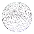 |  | 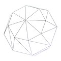 |
|---|---|---|---|---|---|
| Vertices | ~5500 | ~2880 | ~1580 | ~670 | 140 |
| Notes | Maximum detail, for closeups | Minimum detail, very far objects |
To simulate a realistic transform bound scenario, an ad-hoc written application can be used. The use of simple algorithms and minimum fragment operations ensures that CPU bounding does not occur. Each frame, the program will compute each sphere's distance and choose a model from a pool according to this information. To easily show the concept, the distance at which each model is used is hard coded in the source. A more involved method would compute adequate models according to the usage distance chosen.
OpenGL is used for rendering due to its high efficiency in managing small batches, storing each model in a display list thus avoiding communication overheads. Additional vertex load is given by applying two directional light sources ideally located infinitely far away.
The following table compares the performance of LOD aware rendering and a full detail (brute force) method.
| Brute | DLOD | Comparison | |
|---|---|---|---|
| Rendered images |  |  |  |
| Render time | 27.27 ms | 1.29 ms | 21 × reduction |
| Scene vertices | 2,328,480 | 109,440 | 21 × reduction |
Hierarchical LOD
Because hardware is geared towards large amounts of detail, rendering low polygon objects may score sub-optimal performances. HLOD avoids the problem by grouping different objects together . This allows for higher efficiency as well as taking advantage of proximity considerations.