Axes conventions

Last updated
Heading, elevation and bank angles (Z-Y'-X'') for an aircraft. The aircraft's pitch and yaw axes Y and Z are not shown, and its fixed reference frame xyz has been shifted backwards from its center of gravity (preserving angles) for clarity. Axes named according to the air norm DIN 9300 Plane.svg
Heading, elevation and bank angles (Z-Y’-X’’) for an aircraft. The aircraft's pitch and yaw axes Y and Z are not shown, and its fixed reference frame xyz has been shifted backwards from its center of gravity (preserving angles) for clarity. Axes named according to the air norm DIN 9300

In ballistics and flight dynamics, axes conventions are standardized ways of establishing the location and orientation of coordinate axes for use as a frame of reference. Mobile objects are normally tracked from an external frame considered fixed. Other frames can be defined on those mobile objects to deal with relative positions for other objects. Finally, attitudes or orientations can be described by a relationship between the external frame and the one defined over the mobile object.

Contents

The orientation of a vehicle is normally referred to as attitude. It is described normally by the orientation of a frame fixed in the body relative to a fixed reference frame. The attitude is described by attitude coordinates, and consists of at least three coordinates. [1]

While from a geometrical point of view the different methods to describe orientations are defined using only some reference frames, in engineering applications it is important also to describe how these frames are attached to the lab and the body in motion.

Due to the special importance of international conventions in air vehicles, several organizations have published standards to be followed. For example, German DIN has published the DIN 9300 norm for aircraft [2] (adopted by ISO as ISO 1151–2:1985).

Earth bounded axes conventions

Representation of the Earth with parallels and meridians Sphere wireframe.svg
Representation of the Earth with parallels and meridians

World reference frames: ENU and NED

Basically, as lab frame or reference frame, there are two kinds of conventions for the frames:

This frame referenced w.r.t. Global Reference frames like Earth Center Earth Fixed (ECEF) non-inertial system.

World reference frames for attitude description

To establish a standard convention to describe attitudes, it is required to establish at least the axes of the reference system and the axes of the rigid body or vehicle. When an ambiguous notation system is used (such as Euler angles) the convention used should also be stated. Nevertheless, most used notations (matrices and quaternions) are unambiguous.

Earth Centered Earth Fixed and East, North, Up coordinates. ECEF ENU Longitude Latitude relationships.svg
Earth Centered Earth Fixed and East, North, Up coordinates.

Tait–Bryan angles are often used to describe a vehicle's attitude with respect to a chosen reference frame, though any other notation can be used. The positive x-axis in vehicles points always in the direction of movement. For positive y- and z-axis, we have to face two different conventions:

  • In case of land vehicles like cars, tanks etc., which use the ENU-system (East-North-Up) as external reference (World frame), the vehicle's (body's) positive y- or pitch axis always points to its left, and the positive z- or yaw axis always points up. World frame's origin is fixed at the center of gravity of the vehicle. [3]
  • By contrast, in case of air and sea vehicles like submarines, ships, airplanes etc., which use the NED-system (North-East-Down) as external reference (World frame), the vehicle's (body's) positive y- or pitch axis always points to its right, and its positive z- or yaw axis always points down. World frame's origin is fixed at the center of gravity of the vehicle.
  • Finally, in case of space vehicles like the Space Shuttle etc., a modification of the latter convention is used, where the vehicle's (body's) positive y- or pitch axis again always points to its right, and its positive z- or yaw axis always points down, but “down” now may have two different meanings: If a so-called local frame is used as external reference, its positive z-axis points “down” to the center of the Earth as it does in case of the earlier mentioned NED-system, [4] but if the inertial frame is used as reference, its positive z-axis will point now to the north celestial pole, and its positive x-axis to the Vernal Equinox [5] or some other reference meridian.

Frames mounted on vehicles

Specially for aircraft, these frames do not need to agree with the earth-bound frames in the up-down line. It must be agreed what ENU and NED mean in this context.

Conventions for land vehicles

RPY angles of cars and other land vehicles RPY angles of cars.png
RPY angles of cars and other land vehicles

For land vehicles it is rare to describe their complete orientation, except when speaking about electronic stability control or satellite navigation. In this case, the convention is normally the one of the adjacent drawing, where RPY stands for roll-pitch-yaw.

Conventions for sea vehicles

RPY angles of ships and other sea vehicles RPY angles of ships.png
RPY angles of ships and other sea vehicles

As well as aircraft, the same terminology is used for the motion of ships and boats. Some words commonly used were introduced in maritime navigation. For example, the yaw angle or heading, has a nautical origin, with the meaning of "bending out of the course". Etymologically, it is related with the verb 'to go'. [6] It is related to the concept of bearing. It is typically assigned the shorthand notation ψ. [7]

Conventions for aircraft local reference frames

RPY angles of airplanes and other air vehicles RPY angles of airplanes.png
RPY angles of airplanes and other air vehicles
Mnemonics to remember angle names Roll pitch yaw mnemonic.svg
Mnemonics to remember angle names

Coordinates to describe an aircraft attitude (Heading, Elevation and Bank) are normally given relative to a reference control frame located in a control tower, and therefore ENU, relative to the position of the control tower on the earth surface.

Coordinates to describe observations made from an aircraft are normally given relative to its intrinsic axes, but normally using as positive the coordinate pointing downwards, where the interesting points are located. Therefore, they are normally NED.

These axes are normally taken so that X axis is the longitudinal axis pointing ahead, Z axis is the vertical axis pointing downwards, and the Y axis is the lateral one, pointing in such a way that the frame is right-handed.

The motion of an aircraft is often described in terms of rotation about these axes, so rotation about the X-axis is called rolling, rotation about the Y-axis is called pitching, and rotation about the Z-axis is called yawing.

Frames for space navigation

Different reference systems for coordinates in space Celestial.png
Different reference systems for coordinates in space

For satellites orbiting the Earth it is normal to use the Equatorial coordinate system. The projection of the Earth's equator onto the celestial sphere is called the celestial equator. Similarly, the projections of the Earth's north and south geographic poles become the north and south celestial poles, respectively.

Deep space satellites use other Celestial coordinate system, like the Ecliptic coordinate system.

Local conventions for space ships as satellites

RPY angles of spaceships (local frame).png
RPY angles of spaceships (inertial frame).png
RPY angles of the Space Shuttle and other space vehicles, first using a local frame as reference and second using an inertial frame as reference.

If the goal is to keep the shuttle during its orbits in a constant attitude with respect to the sky, e.g. in order to perform certain astronomical observations, the preferred reference is the inertial frame, and the RPY angle vector (0|0|0) describes an attitude then, where the shuttle's wings are kept permanently parallel to the Earth's equator, its nose points permanently to the vernal equinox, and its belly towards the northern polar star (see picture). (Note that rockets and missiles more commonly follow the conventions for aircraft where the RPY angle vector (0|0|0) points north, rather than toward the vernal equinox).

On the other hand, if the goal is to keep the shuttle during its orbits in a constant attitude with respect to the surface of the Earth, the preferred reference will be the local frame, with the RPY angle vector (0|0|0) describing an attitude where the shuttle's wings are parallel to the Earth's surface, its nose points to its heading, and its belly down towards the centre of the Earth (see picture).

Frames used to describe attitudes

Normally the frames used to describe a vehicle's local observations are the same frames used to describe its attitude with respect to the ground tracking stations. i.e. if an ENU frame is used in a tracking station, also ENU frames are used onboard and these frames are also used to refer local observations.

An important case in which this does not apply is aircraft. Aircraft observations are performed downwards and therefore normally NED axes convention applies. Nevertheless, when attitudes with respect to ground stations are given, a relationship between the local earth-bound frame and the onboard ENU frame is used.

See also

Related Research Articles

<span class="mw-page-title-main">Gyroscope</span> Device for measuring or maintaining orientation and angular velocity

A gyroscope is a device used for measuring or maintaining orientation and angular velocity. It is a spinning wheel or disc in which the axis of rotation is free to assume any orientation by itself. When rotating, the orientation of this axis is unaffected by tilting or rotation of the mounting, according to the conservation of angular momentum.

<span class="mw-page-title-main">Equatorial coordinate system</span> Celestial coordinate system used to specify the positions of celestial objects

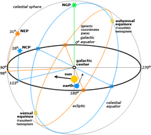
The equatorial coordinate system is a celestial coordinate system widely used to specify the positions of celestial objects. It may be implemented in spherical or rectangular coordinates, both defined by an origin at the centre of Earth, a fundamental plane consisting of the projection of Earth's equator onto the celestial sphere, a primary direction towards the vernal equinox, and a right-handed convention.

<span class="mw-page-title-main">Aircraft flight dynamics</span> Science of air vehicle orientation and control in three dimensions

Flight dynamics is the science of air vehicle orientation and control in three dimensions. The three critical flight dynamics parameters are the angles of rotation in three dimensions about the vehicle's center of gravity (cg), known as pitch, roll and yaw. These are collectively known as aircraft attitude, often principally relative to the atmospheric frame in normal flight, but also relative to terrain during takeoff or landing, or when operating at low elevation. The concept of attitude is not specific to fixed-wing aircraft, but also extends to rotary aircraft such as helicopters, and dirigibles, where the flight dynamics involved in establishing and controlling attitude are entirely different.

<span class="mw-page-title-main">Gimbal lock</span> Loss of one degree of freedom in a three-dimensional, three-gimbal mechanism

Gimbal lock is the loss of one degree of freedom in a multi-dimensional mechanism at certain alignments of the axes. In a three-dimensional three-gimbal mechanism, gimbal lock occurs when the axes of two of the gimbals are driven into a parallel configuration, "locking" the system into rotation in a degenerate two-dimensional space.

<span class="mw-page-title-main">Euler angles</span> Description of the orientation of a rigid body

The Euler angles are three angles introduced by Leonhard Euler to describe the orientation of a rigid body with respect to a fixed coordinate system.

<span class="mw-page-title-main">Rigid body</span> Physical object which does not deform when forces or moments are exerted on it

In physics, a rigid body, also known as a rigid object, is a solid body in which deformation is zero or negligible. The distance between any two given points on a rigid body remains constant in time regardless of external forces or moments exerted on it. A rigid body is usually considered as a continuous distribution of mass.

<span class="mw-page-title-main">Orbital state vectors</span> Cartesian vectors of position and velocity of an orbiting body in space

In astrodynamics and celestial dynamics, the orbital state vectors of an orbit are Cartesian vectors of position and velocity that together with their time (epoch) uniquely determine the trajectory of the orbiting body in space.

A fictitious force is a force that appears to act on a mass whose motion is described using a non-inertial frame of reference, such as a linearly accelerating or rotating reference frame. Fictitious forces are invoked to maintain the validity and thus use of Newton's second law of motion, in frames of reference which are not inertial.

The International Celestial Reference System (ICRS) is the current standard celestial reference system adopted by the International Astronomical Union (IAU). Its origin is at the barycenter of the Solar System, with axes that are intended to "show no global rotation with respect to a set of distant extragalactic objects". This fixed reference system differs from previous reference systems, which had been based on Catalogues of Fundamental Stars that had published the positions of stars based on direct "observations of [their] equatorial coordinates, right ascension and declination" and had adopted as "privileged axes ... the mean equator and the dynamical equinox" at a particular date and time.

<span class="mw-page-title-main">Orientation (geometry)</span> Notion of pointing in a direction

In geometry, the orientation, attitude, bearing, direction, or angular position of an object – such as a line, plane or rigid body – is part of the description of how it is placed in the space it occupies. More specifically, it refers to the imaginary rotation that is needed to move the object from a reference placement to its current placement. A rotation may not be enough to reach the current placement, in which case it may be necessary to add an imaginary translation to change the object's position. The position and orientation together fully describe how the object is placed in space. The above-mentioned imaginary rotation and translation may be thought to occur in any order, as the orientation of an object does not change when it translates, and its position does not change when it rotates.

<span class="mw-page-title-main">Earth-centered, Earth-fixed coordinate system</span> 3-D coordinate system centered on the Earth

The Earth-centered, Earth-fixed coordinate system, also known as the geocentric coordinate system, is a cartesian spatial reference system that represents locations in the vicinity of the Earth as X, Y, and Z measurements from its center of mass. Its most common use is in tracking the orbits of satellites and in satellite navigation systems for measuring locations on the surface of the Earth, but it is also used in applications such as tracking crustal motion.

<span class="mw-page-title-main">Local tangent plane coordinates</span> Geographic coordinate system

Local tangent plane coordinates (LTP), also known as local ellipsoidal system, local geodetic coordinate system, or local vertical, local horizontal coordinates (LVLH), are a spatial reference system based on the tangent plane defined by the local vertical direction and the Earth's axis of rotation. It consists of three coordinates: one represents the position along the northern axis, one along the local eastern axis, and one represents the vertical position. Two right-handed variants exist: east, north, up (ENU) coordinates and north, east, down (NED) coordinates. They serve for representing state vectors that are commonly used in aviation and marine cybernetics.

<span class="mw-page-title-main">Stability derivatives</span>

Stability derivatives, and also control derivatives, are measures of how particular forces and moments on an aircraft change as other parameters related to stability change. For a defined "trim" flight condition, changes and oscillations occur in these parameters. Equations of motion are used to analyze these changes and oscillations. Stability and control derivatives are used to linearize (simplify) these equations of motion so the stability of the vehicle can be more readily analyzed.

<span class="mw-page-title-main">Aircraft principal axes</span> Principal directions in aviation

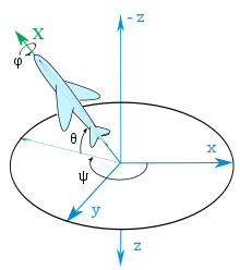
An aircraft in flight is free to rotate in three dimensions: yaw, nose left or right about an axis running up and down; pitch, nose up or down about an axis running from wing to wing; and roll, rotation about an axis running from nose to tail. The axes are alternatively designated as vertical, lateral, and longitudinal respectively. These axes move with the vehicle and rotate relative to the Earth along with the craft. These definitions were analogously applied to spacecraft when the first crewed spacecraft were designed in the late 1950s.

<span class="mw-page-title-main">Earth-centered inertial</span> Coordinate frames

Earth-centered inertial (ECI) coordinate frames have their origins at the center of mass of Earth and are fixed with respect to the stars. "I" in "ECI" stands for inertial, in contrast to the "Earth-centered – Earth-fixed" (ECEF) frames, which remains fixed with respect to Earth's surface in its rotation, and then rotates with respect to stars.

<span class="mw-page-title-main">Inertial navigation system</span> Continuously computed dead reckoning

An inertial navigation system is a navigation device that uses motion sensors (accelerometers), rotation sensors (gyroscopes) and a computer to continuously calculate by dead reckoning the position, the orientation, and the velocity of a moving object without the need for external references. Often the inertial sensors are supplemented by a barometric altimeter and sometimes by magnetic sensors (magnetometers) and/or speed measuring devices. INSs are used on mobile robots and on vehicles such as ships, aircraft, submarines, guided missiles, and spacecraft. Older INS systems generally used an inertial platform as their mounting point to the vehicle and the terms are sometimes considered synonymous.

<span class="mw-page-title-main">Yaw (rotation)</span> Rotation of a vehicle about its vertical axis

A yaw rotation is a movement around the yaw axis of a rigid body that changes the direction it is pointing, to the left or right of its direction of motion. The yaw rate or yaw velocity of a car, aircraft, projectile or other rigid body is the angular velocity of this rotation, or rate of change of the heading angle when the aircraft is horizontal. It is commonly measured in degrees per second or radians per second.

Spacecraft attitude control is the process of controlling the orientation of a spacecraft with respect to an inertial frame of reference or another entity such as the celestial sphere, certain fields, and nearby objects, etc.

In physics and engineering, Davenport chained rotations are three chained intrinsic rotations about body-fixed specific axes. Euler rotations and Tait–Bryan rotations are particular cases of the Davenport general rotation decomposition. The angles of rotation are called Davenport angles because the general problem of decomposing a rotation in a sequence of three was studied first by Paul B. Davenport.

<span class="mw-page-title-main">Steady flight</span>

Steady flight, unaccelerated flight, or equilibrium flight is a special case in flight dynamics where the aircraft's linear and angular velocity are constant in a body-fixed reference frame. Basic aircraft maneuvers such as level flight, climbs and descents, and coordinated turns can be modeled as steady flight maneuvers. Typical aircraft flight consists of a series of steady flight maneuvers connected by brief, accelerated transitions. Because of this, primary applications of steady flight models include aircraft design, assessment of aircraft performance, flight planning, and using steady flight states as the equilibrium conditions around which flight dynamics equations are expanded.

References

  1. Hanspeter Schaub; John L. Junkins (2003). "Rigid body kinematics". Analytical mechanics of space systems. American Institute of Aeronautics and Astronautics. p. 71. ISBN   1-56347-563-4.
  2. Luft- und Raumfahrt; Begriffe, Größen und Formelzeichen der Flugmechanik; Bewegungen des Luftfahrzeugs und der Atmosphäre gegenüber der Erde
  3. NavCommand. Software to Operate and Configure iMAR Inertial Measuring and Surveying Systems. Operation and User Instructions. St.Ingbert 2007, str.11–12. http://www.imar-navigation.de/download/nav_command_en.pdf Archived 2006-09-23 at the Wayback Machine
  4. Exploration: Local Reference Orbiter Attitude (September 18, 1995) "LVLH Attitude". Archived from the original on 2007-07-14. Retrieved 2010-10-08. (article no more available since 2007)
  5. Exploration: Inertial Reference Orbiter Attitude (October 3, 1995) "Inertial Attitude". Archived from the original on 2007-07-14. Retrieved 2010-10-08. (article no more available since 2007)
  6. Etymology online dictionary Archived November 15, 2010, at the Wayback Machine
  7. Hurt, H. H. Jr. (January 1965) [1960]. Aerodynamics for Naval Aviators. U.S. Government Printing Office, Washington D.C.: U.S. Navy, Aviation Training Division. p. 284. NAVWEPS 00-80T-80.