Brake-by-wire

Last updated
SpeedE, an academic concept car developed for studying drive-by-wire technologies such as brake-by-wire Erprobungsfahrzeug SpeedE der fka GmbH.jpg
SpeedE, an academic concept car developed for studying drive-by-wire technologies such as brake-by-wire

Brake-by-wire technology in the automotive industry is the ability to control brakes through electronic means, without a mechanical connection that transfers force to the physical braking system from a driver input apparatus such as a pedal or lever. [1]

Contents

The three main types of brake-by-wire systems are: electronic parking brakes which have, since the turn of the 21st century, become more common; electro-hydraulic brakes (EHB) which can be implemented alongside legacy hydraulic brakes and as of 2020 have found small-scale usage in the automotive industry; and electro-mechanical brakes (EMB) that use no hydraulic fluid, which as of 2020 have yet to be successfully introduced in production vehicles. [1]

Electro-hydraulic braking systems control or boost the pressure applied to the hydraulic pumps through the brake pedal. Safety requires that the system remains fail-operational in the event of a power failure or an electronic software or hardware fault. Traditionally this has been achieved by means of a mechanical linkage between the brake pedal and the brake master cylinder. With a mechanical linkage, the braking system still operates hydraulically via the pedal, whether or not electrical control is present. [2] EHBs can be implemented by-wire, without legacy hydraulic systems and mechanical connections. In such a case, fail-operational redundancy is implemented, allowing the vehicle to brake even if some of the brake systems fail. [1]

Electro-mechanical brakes offer the advantage of reduced braking system volume and weight, less maintenance, easier compatibility with active safety control systems, and absence of toxic braking fluid. Their novel actuation methods such as wedge brakes have kept them, as of 2020, from successfully being introduced in production vehicles. [1]

Since by-wire systems have no mechanical linkages that would provide manual control over the brakes, they require fail-operational redundancy as specified by the ISO 26262 standard level D. [3] Redundant power supplies, sensors, and communication networks are required. [1]

Implementations

Prevalence

Some x-by-wire technologies have been already installed on commercial vehicles such as steer-by-wire, and throttle-by-wire. Brake-by-wire technology has been widely commercialized with the introduction of Battery Electric Vehicles and Hybrid Vehicles. The most widely used application by Toyota in the high volume Prius was preceded by the GM EV1, the Rav4 EV, and other EVs where the technology is required for regenerative braking. Ford, General Motors, and most other manufacturers use the same general design, with the exception of Honda, who designed a notably different design.

Brake-by-wire is used in most common hybrid and electric vehicles produced since 1998 including all Toyota, Ford, and General Motors Electric and hybrid models. The Toyota Synergy Drive and the Rav4 EV use a system where a modified ABS (antilock brake system) actuator is coupled with a special hydraulic brake master cylinder to create a hydraulic system, coupled with the brake control unit (computer). Ford's system is almost identical to the Toyota system, and the General Motors system uses different nomenclature for components while the operation is virtually identical.

Electro-hydraulic brakes

The hydraulic force generated by pressing the brake pedal is used only as a sensor input to the computer unless a catastrophic failure occurs including a loss of 12-volt electrical power. The brake actuator has an electric pump that provides the hydraulic pressure for the system, and valves to pressurize each wheel caliper to apply the friction brake when required by the system.

The system includes all of the complexity of a vehicle stability control system (VSC), antilock brake system (ABS), and the requirement to use the Regeneration Braking as the primary mode of slowing the vehicle unless the Traction Battery (high-voltage battery) state of charge is too high to accept the additional energy or a panic stop or ABS situation is detected by the system.

The sensors monitored as inputs for the brake system include the wheel speed sensors, traction battery state of charge, yaw sensor, brake pedal stroke sensor, steering wheel angle, hydraulic actuator pressure, hydraulic pressures of each wheel caliper circuit, and accelerator position. Other information and inputs are also monitored.

The standard or typical operation is as follows:

  1. The vehicle operator presses the brake pedal
  2. The master cylinder converts the brake pedal movement to hydraulic pressure
  3. the stroke sensor measures the pedal movement to identify a "panic stop" condition
  4. The pressure transducer provides the brake force desired.
  5. The Brake Control Unit (computer) detects the inputs, and then checks the wheel speed sensors to determine vehicle speed, and to determine if a wheel lockup requires the ABS algorithm.
  6. The Brake Control System then checks the yaw sensor, steering wheel angle, and state of charge of the traction battery.
  7. If the speed of the vehicle is above about 7 MPH, the vehicle traction motor generator is used as a generator to convert the kinetic energy to electric power, and stores the energy in the battery. This slows the vehicle.
  8. If the operator (driver) presses the brake pedal harder, the system will apply hydraulic friction brakes to increase brake force.
  9. Once the vehicle speed drops below about 7 MPH, the hydraulic brake system will completely take over, as regenerative Braking does not work effectively.
  10. If the yaw sensor detects vehicle yaw, the system will initiate vehicle stability algorithms and processes (VSC).
  11. If the wheel speed sensors detect wheel lock-up, the system will initiate anti-lock algorithm (ABS).

EBS

Brake-by-wire exists on heavy duty commercial vehicles under the name Electronic Braking System (EBS). This system provides electronic activation of all braking system components including retarder and engine brake. EBS also supports trailers and communicates between the towing vehicle and trailer using the ISO 11992 protocol. The communication between trailer and towing vehicle shall be done through a specific connector dedicated to ABS/EBS following either ISO 7638-1 for 24 V systems or ISO 7638-2 for 12 V systems.

EBS still relies on compressed air for braking and is only controlling the air through valves which means that it is not depending on higher voltages used by the electromechanical or electrohydraulical brake systems where electric power also is used to apply the brake pressure.

EBS enhances the precision of the braking over conventional braking, which shortens the braking distance. The fall back of an EBS system in case of failure is to use the ordinary air brake control pressure, so even in the event of a failure of the electronics the vehicle shall be able to make a safe stop.

Electro-mechanical brakes

General architecture of an EMB system Brake by wire architecture-01.jpg
General architecture of an EMB system

General architecture of an electromechanical braking (EMB) system in a drive-by-wire car is shown in Fig. 1. The system mainly comprises five types of elements:

  1. Processors including an electronic control unit (ECU) and other local processors
  2. Memory (mainly integrated into the ECU)
  3. Sensors
  4. Actuators
  5. Communication network(s).

Once the driver inputs a brake command to the system via a human–machine interface – HMI (e.g. the brake pedal), four independent brake commands are generated by the ECU based on high level brake functions such as anti-lock braking system (ABS) or vehicle stability control (VSC). These command signals are sent to the four electric calipers (e-calipers) via a communication network. As this network might not be able to properly communicate with the e-calipers due to network faults, HMI sensory data are also directly transmitted to each e-caliper via a separate data bus.

In each e-caliper a controller uses the brake command (received from ECU) as a reference input. The controller provides drive control commands for a power control module. This module controls three phase drive currents for the brake actuator which is a permanent magnet DC motor, energised by 42 V sources. In addition to tracking its reference brake command, the caliper controller also controls the position and speed of the brake actuator. Thus, two sensors are vitally required to measure the position and speed of the actuator in each e-caliper. Because of the safety critical nature of the application, even missing a limited number of samples of these sensory data should be compensated for.

Voting

A brake-by-wire system, by nature, is a safety critical system and therefore fault tolerance is a vitally important characteristic of this system. As a result, a brake-by-wire system is designed in such way that many of its essential information would be derived from a variety of sources (sensors) and be handled by more than the bare necessity hardware. Three main types of redundancy usually exist in a brake-by-wire system:

  1. Redundant sensors in safety critical components such as the brake pedal.
  2. Redundant copies of some signals that are of particular safety importance such as displacement and force measurements of the brake pedal copied by multiple processors in the pedal interface unit.
  3. Redundant hardware to perform important processing tasks such as multiple processors for the ECU in Fig. 1.

To use the existing redundancy, voting algorithms need to be evaluated, modified and adopted to meet the stringent requirements of a brake-by-wire system. Reliability, fault tolerance and accuracy are the main targeted outcomes of the voting techniques that should be developed especially for redundancy resolution inside a brake-by-wire system.

Example of a solution for this problem: A fuzzy voter developed to fuse the information provided by three sensors devised in a brake pedal design.

Missing data compensation

In a brake-by-wire car, some sensors are safety-critical components, and their failure will disrupt the vehicle function and endanger human lives. Two examples are the brake pedal sensors and the wheel speed sensors. The electronic control unit must always be informed of the driver's intentions to brake or to stop the vehicle. Therefore, missing the pedal sensor data is a serious problem for functionality of the vehicle control system.

In the current brake-by-wire systems used in passenger and light truck vehicles, the system is designed to use existing sensors that have been proven to be dependable in brake system components and systems including ABS and VSC systems.

The highest potential risk for brake system failure has proven to be the Brake Control System software. Recurring failures have occurred in over 200 cases documented in NTSB documents. Because each manufacturer guards the confidentiality of their system design and software, there is no independent validation of the systems.

As of 2016 the NTSB has not directly investigated passenger car and light truck brake-by-wire vehicle accidents, and the manufacturers have taken the position that their vehicles are completely safe, and that all reported accidents are the result of "driver error".

Wheel speed data are also vital in a brake-by-wire system to avoid skidding. The design of a brake-by-wire car should provide safeguards against missing some of the data samples provided by the safety-critical sensors. Popular solutions are to provide redundant sensors and to apply a fail-safe mechanism. In addition to a complete sensor loss, the electronic control unit may also suffer an intermittent (temporary) data loss. For example, sensor data can sometimes fail to reach the electronic control unit. This may happen due to a temporary problem with the sensor itself or with the data transmission path. It may also result from an instantaneous short circuit or disconnection, a communication network fault, or a sudden increase in noise. In such cases, for a safe operation, the system has to be compensated for missing data samples.

Example of a solution for this problem: Missing data compensation by a predictive filter.

Accurate estimation of position and speed of brake actuators in the e-calipers

The caliper controller controls the position and speed of the brake actuator (besides its main task which is tracking of its reference brake command). Thus, position and speed sensors are vitally required in each e-caliper and an efficient design of a measurement mechanism to sense the position and speed of the actuator is required. Recent designs for brake-by-wire systems use resolvers to provide accurate and continuous measurements for both absolute position and speed of the rotor of the actuators. Incremental encoders are relative position sensors and their additive error needs to be calibrated or compensated for by different methods. Unlike the encoders, resolvers provide two output signals that always allow the detection of absolute angular position. In addition, they suppress common mode noise and are especially useful in a noisy environment. Because of these reasons, resolvers are usually applied for the purpose of position and speed measurement in brake-by-wire systems. However, nonlinear and robust observers are required to extract accurate position and speed estimates from the sinusoidal signals provided by resolvers.

Example of a solution for this problem: A hybrid resolver-to-digital conversion scheme with guaranteed robust stability and automatic calibration of the resolvers used in an EMB system.

Measurement and/or estimation of clamp force in the electromechanical calipers

A clamp force sensor is a relatively expensive component in an EMB caliper. The cost is derived from its high unit value from a supplier, as well as marked production expenses because of its inclusion. The later emanates from the complex assembly procedures dealing with small tolerances, as well as on-line calibration for performance variability from one clamp force sensor to another. The successful use of a clamp force sensor in an EMB system poses a challenging engineering task. If a clamp force sensor is placed close to a brake pad, then it will be subjected to severe temperature conditions reaching up to 800 Celsius that will challenge its mechanical integrity. Also temperature drifts must be compensated for. This situation can be avoided by embedding a clamp force sensor deep within the caliper. However, embedding this sensor leads to hysteresis that is influenced by friction between the clamp force sensor and the point of contact of an inner pad with the rotor. This hysteresis prevents a true clamp force to be measured. Due to the cost issues and engineering challenges involved with including the clamp force sensor, it might be desirable to eliminate this component from the EMB system. A potential opportunity to achieve this presents itself in accurate estimation of the clamp force based on alternative EMB system sensory measurements leading to the omission of a clamp force sensor.

Example of a solution for this problem: Clamp force estimation from actuator position and current measurements using sensor data fusion.

Electric parking brakes

Brake by wire is now a mature concept in its application to vehicle parking brakes. The electronic parking brake (EPB) was introduced in the early 2000s by BMW and Audi on their top line models (the 7 Series and A8 respectively) to dispense with the traditional cable operated system (operated via a lever between the seats or via a foot pedal) which commonly acted on the rear wheels of a car. EPBs, however, use a motorized mechanism built into the rear disc brake caliper, and is signalled via a switch on the centre console or dashboard. The electric parking brake is normally integrated with the vehicle's other systems via a CAN bus network, and can provide additional functionality such as

EPB systems afford packaging and manufacturing advances, since it allows for an uncluttered central console in the absence of the traditional handbrake lever (many manufacturers have used the freed up space to place the controls for their infotainment systems), plus it reduces manufacturing complexity since it removes the need to route bowden cables underneath the vehicle.

EPB has gradually filtered down to cheaper vehicles, for instance within the Volkswagen Group, EPB became now a standard fitment on the 2006 Passat (B6), whilst Opel introduced it on the 2008 Insignia.

See also

Related Research Articles

<span class="mw-page-title-main">Anti-lock braking system</span> Safety anti-skid braking system used on aircraft and land vehicles

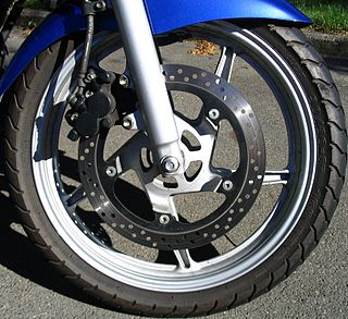
An anti-lock braking system (ABS) is a safety anti-skid braking system used on aircraft and on land vehicles, such as cars, motorcycles, trucks, and buses. ABS operates by preventing the wheels from locking up during braking, thereby maintaining tractive contact with the road surface and allowing the driver to maintain more control over the vehicle.

<span class="mw-page-title-main">Brake</span> Mechanical device that inhibits motion

A brake is a mechanical device that inhibits motion by absorbing energy from a moving system. It is used for slowing or stopping a moving vehicle, wheel, axle, or to prevent its motion, most often accomplished by means of friction.

<span class="mw-page-title-main">Bicycle brake</span> Braking device for bicycles

A bicycle brake reduces the speed of a bicycle or prevents it from moving. The three main types are: rim brakes, disc brakes, and drum brakes.

<span class="mw-page-title-main">Automatic transmission</span> Type of motor vehicle transmission that automatically changes gear ratio as the vehicle moves

An automatic transmission is a multi-speed transmission used in motor vehicles that does not require any input from the driver to change forward gears under normal driving conditions. Vehicles with internal combustion engines, unlike electric vehicles, require the engine to operate in a narrow range of rates of rotation, requiring a gearbox, operated manually or automatically, to drive the wheels over a wide range of speeds.

<span class="mw-page-title-main">Electronic stability control</span> Computerized safety automotive technology

Electronic stability control (ESC), also referred to as electronic stability program (ESP) or dynamic stability control (DSC), is a computerized technology that improves a vehicle's stability by detecting and reducing loss of traction (skidding). When ESC detects loss of steering control, it automatically applies the brakes to help steer the vehicle where the driver intends to go. Braking is automatically applied to wheels individually, such as the outer front wheel to counter oversteer, or the inner rear wheel to counter understeer. Some ESC systems also reduce engine power until control is regained. ESC does not improve a vehicle's cornering performance; instead, it helps reduce the chance of the driver losing control of the vehicle.

A traction control system (TCS), is typically a secondary function of the electronic stability control (ESC) on production motor vehicles, designed to prevent loss of traction of the driven road wheels. TCS is activated when throttle input and engine power and torque transfer are mismatched to the road surface conditions.

<span class="mw-page-title-main">Quattro (four-wheel-drive system)</span> Sub-brand by Audi

Quattro is the trademark used by the automotive brand Audi to indicate that all-wheel drive (AWD) technologies or systems are used on specific models of its automobiles.

<span class="mw-page-title-main">Electronic brakeforce distribution</span>

Electronic brakeforce distribution or electronic brakeforce limitation (EBL) is an automobile brake technology that automatically varies the amount of force applied to each of a vehicle's wheels, based on road conditions, speed, loading, etc, thus providing intelligent control of both brake balance and overall brake force. Always coupled with anti-lock braking systems (ABS), EBD can apply more or less braking pressure to each wheel in order to maximize stopping power whilst maintaining vehicular control. Typically, the front end carries more weight and EBD distributes less braking pressure to the rear brakes so the rear brakes do not lock up and cause a skid. In some systems, EBD distributes more braking pressure at the rear brakes during initial brake application before the effects of weight transfer become apparent.

<span class="mw-page-title-main">Drive by wire</span> Automotive technology

Drive by wire or DbW technology in the automotive industry is the use of electronic or electro-mechanical systems in place of mechanical linkages that control driving functions. The concept is similar to fly-by-wire in the aviation industry. Drive-by-wire may refer to just the propulsion of the vehicle through electronic throttle control, or it may refer to electronic control over propulsion as well as steering and braking, which separately are known as steer by wire and brake by wire, along with electronic control over other vehicle driving functions.

<span class="mw-page-title-main">Automated manual transmission</span> Type of multi-speed motor vehicle transmission system

The automated manual transmission (AMT) is a type of transmission for motor vehicles. It is essentially a conventional manual transmission equipped with automatic actuation to operate the clutch and/or shift gears.

<span class="mw-page-title-main">Hydraulic brake</span> Arrangement of braking mechanism

A hydraulic brake is an arrangement of braking mechanism which uses brake fluid, typically containing glycol ethers or diethylene glycol, to transfer pressure from the controlling mechanism to the braking mechanism.

<span class="mw-page-title-main">Parking brake</span> Secondary automotive braking system

In road vehicles, the parking brake, also known as a handbrake or emergency brake (e-brake), is a mechanism used to keep the vehicle securely motionless when parked. Parking brakes often consist of a pulling mechanism attached to a cable which is connected to two wheel brakes. In most vehicles, the parking brake operates only on the rear wheels, which have reduced traction while braking. The mechanism may be a hand-operated lever, a straight pull handle located near the steering column, or a foot-operated pedal located with the other pedals.

A transmission control unit (TCU), also known as a transmission control module (TCM), or a gearbox control unit (GCU), is a type of automotive ECU that is used to control electronic automatic transmissions. Similar systems are used in conjunction with various semi-automatic transmissions, purely for clutch automation and actuation. A TCU in a modern automatic transmission generally uses sensors from the vehicle, as well as data provided by the engine control unit (ECU), to calculate how and when to change gears in the vehicle for optimum performance, fuel economy and shift quality.

<span class="mw-page-title-main">Digifant engine management system</span>

The Digifant engine management system is an electronic engine control unit (ECU), which monitors and controls the fuel injection and ignition systems in petrol engines, designed by Volkswagen Group, in cooperation with Robert Bosch GmbH.

S-AWC is the brand name of an advanced full-time four-wheel drive system developed by Mitsubishi Motors. The technology, specifically developed for the new 2007 Lancer Evolution, the 2010 Outlander, the 2014 Outlander, the Outlander PHEV and the Eclipse Cross have an advanced version of Mitsubishi Motors' AWC system. Mitsubishi Motors first exhibited S-AWC integration control technology in the Concept-X model at the 39th Tokyo Motor Show in 2005. According to Mitsubishi Motors, "the ultimate embodiment of the company's AWC philosophy is the S-AWC system, a 4WD-based integrated vehicle dynamics control system".

All Wheel Control (AWC) is the brand name of a four-wheel drive (4WD) system developed by Mitsubishi Motors. The system was first incorporated in the 2001 Lancer Evolution VII. Subsequent developments have led to S-AWC (Super All Wheel Control), developed specifically for the new 2007 Lancer Evolution. The system is referred by the company as its unique 4-wheel drive technology umbrella, cultivated through its motor sports activities and long history in rally racing spanning almost half a century.

<span class="mw-page-title-main">Electronic Diesel Control</span>

Electronic Diesel Control is a diesel engine fuel injection control system for the precise metering and delivery of fuel into the combustion chamber of modern diesel engines used in trucks and cars.

Sensotronic Brake Control (SBC) is an electro-hydraulic brake system, where the wheel brake cylinders on a vehicle are operated through a servomechanism.

<span class="mw-page-title-main">Electronic parking brake</span> Parking brake

An electronic parking brake (EPB), also known as an electric parking brake or electric park brake, is an electronically controlled parking brake, whereby the driver activates the holding mechanism with a button and the brake pads are electrically applied to the rear wheels. This is accomplished by an electronic control unit (ECU) and an actuator mechanism. There are two mechanisms that are currently in production, Cable puller systems and Caliper integrated systems. EPB systems can be considered a subset of Brake-by-wire technology.

Power brakes consist of a system of hydraulics used to slow down or stop a motor vehicle. It uses a combination of mechanical components and vacuum assistance to multiply the pressure applied to the brake pedal by the driver into enough force to actuate the brakes and stop the vehicle. By contrast, manual brakes rely solely on the pressure the driver applies to the brake pedal.

References

  1. 1 2 3 4 5 Dieter Schramm; et al. (2020), "5 Braking systems", Vehicle Technology: Technical foundations of current and future motor vehicles, De Gruyter Oldenbourg, doi:10.1515/9783110595703
  2. SpeedE – Forschungsplattform, ika – Institute for Motor Vehicles of RWTH Aachen University, 2016
  3. Dieter Schramm; et al. (2020), "1 Introduction and overview", Vehicle Technology: Technical foundations of current and future motor vehicles, De Gruyter Oldenbourg, doi:10.1515/9783110595703