The expansion bus interface is designed to create an open ecosystem of function modules for high-performance peripheral connectivity. Its main focus is on supporting FPGA and FPGA SoC devices from all major manufacturers like Altera, Lattice, Microchip and Xilinx.
The word "CRUVI" is a combination of the Estonian word "KRUVI" for screw and the letter "C", which refers to the half of the hexagonal screw head. In this case, the "K" was replaced with "C" to emphasize the reference to the screw head.
Overview
It can be used to build high performance prototypes, for system integration and testing to build complex systems from smaller building blocks to iterate quickly and reduce cost. Create custom test systems for production functional testing. It´s a perfect platform for your next high-performance semiconductor evaluation boards and systems.
The carrier module supplies the power supply, the input/output voltage and controls the functions of the peripheral modules.
The CRUVI open standard coexists between low speed, low pin-count like Pmod Interface devices and high-performance, high pin-count (HPC), 400 I/O FPGA Mezzanine Card (FMC) peripherals.
Three board-to-board connectors are specified: CRUVI-LS (Low Speed), CRUVI-HS (High Speed) and CRUVI-GT (Gigabit Transceiver) PCIe Gen 5.0 capable.
Bridging adapter exists to convert signals from Pmod to CRUVI-LS (CR00025), from FMC to CRUVI-HS (CR00101, CR00111) and FMC to CRUVI-GT (CR00112).
History of CRUVI specification
International contributors to define the open source CRUVI specification are Trenz Electronic GmbH, Arrow Electronics, Samtec, Flinders University, Synaptic Laboratories Ltd, Symbiotic EDA and MicroFPGA UG.
The Standardization Group for Embedded Technologies e.V. (SGET) launches its call for participation to establish a new Standard Development Team (SDT) for the FPGA Peripheral Module standard with the working title sCRUVI. The founding meeting of the Standard Development Team (SDT.07) for FPGA Peripheral Modules was on May 6th 2025. This initiative aims to set a groundbreaking standard for peripheral modules used in FPGA and FPGA-SoC-based systems.
Structure and description of the carrier modules
Single, double or triple width modules are allowed and they have more mounting holes.
A triple size of space on carrier board is 67.72 x 57.5mm² (2.66535 x 2.26378 inch²). There are 3 slots. The mounting holes (1 to 6) for M2 screws are 2.2mm (0.0866 inch) diameter and need SMD spacer for mechanically fixing. The CR99201 PCB template has LS and HS connectors named: AX, BY and CZ. The CR99500[3] PCB template has LS, HS and GT connectors.
triple maximum size carrier board
It is recommended for all FPGA host boards with CRUVI slots provide LiteX platform support files.[4]
Structure and description of the peripheral modules
There are different single peripheral module possible, flexible and scalable by size LS, HS and GT connectors. Mounting holes are for M2 screws 2.2mm (0.0866 inch) diameter.
CRUVI connector specification
specification of connectors
LS Low Speed
HS High Speed
GT Gigabit Transceiver
Carrier side connector
CLT-106-02-F-D-A-K
SS4-30-3.50-L-D-K
ADF6-20-03.5-L-4-2
3D STEP Model
Peripheral side connector
TMMH-106-04-F-DV-A-M
ST4-30-1.50-L-D-P
ADM6-20-01.5-L-4-2
3D STEP Model
Pin no
12 (6 per row)
60 (30 per row)
80 (20 per row)
pitch [mm] / [inch]
2 / 0.787
0.4 / 0.016
0.635 / 0.025
stacked height [mm] / [inch]
4.78 to 5.29 /0.188 to 0.208
5 / 0.197
speed rating [GHz] / [Gbps]
5.5 / 11
13.5 / 27 (single ended)
15.5 / 31 (differential)
32
Single ended I/O pins (VCCIO)
8
37 (28 adj.) + (9 fixed 3.3V)
8 + I2C
max. differential I/O
no
max. 12 LVDS
max. 4 lanes + REFCLK
Power Supply
adjustable, 3.3V, 5V
Current rating per pin [A]
4.1 (2-pin powered)
1.6 (2-pin powered)
1.34 (4-pin powered)
max. Temperatur range [°C]
-55 to 125
peripheral board specification
There are different single peripheral module possible, flexible and scalable by size LS, HS and GT connectors. Mounting holes are for M2 screws 2.2mm (0.0866 inch) diameter.
It is recommended to have EEPROM with I2C for identification of peripheral module with a specific address number.
identification EEPROM is included; This template is usefull for I2C, I3C, SPI sensor, I2SPDMMEMS microphones, programmable oscillator, ADC, DAC or SPI (QSPI) Flash memory device in BGA24 or SO-8 package.
14 x 14 / 0.55 x 0.55
LS
CR99002
same as CR99001 with added u.Fl connectors for I/O
22 x 32 / 0.87 x 1.2598
LS
CR99003
maximum size one-wide half-length, identification EEPROM is included
18 x 32 / 0.71 x 1.26
LS
CR99004
This template is usefull to convert into Pmod compatible connector (CR00005).
22 x 30 / 0.87 x 1.18
LS
CR99005
is half-length LS module with two SMA connectors
18 x 20 / 0.71 x 0.79
HS
CR99101
minimal size HS Module; good for HyperRAM or HyperFlash (CR00041), eMMC (CR00049) or loopback adapter for CRUVI-HS (CR00091)
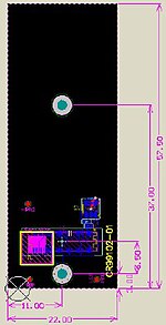
22 x 57.5 / 0.87 x 2.26
HS
CR99102
maximum sized single-width HS module; good for signal test adapter to probed with scope or logic analyzer (CR00026), for high speed interfaces like USB-C, HDMI (CR00240), MIPICSI/DSI, SDIO, xGMIIEthernet (CR0020x) and LVDSADC (1 to 4 data lane)
GT
CR99103
comming soon, good for HDMI output (CR00240), JESD204B ADC (CR00401), loopback adapter for CRUVI-GT (CR00092)
LS Low Speed, HS High Speed and GT Gigabit Transceiver connector
This article has not been added to any content categories. Please help out by adding categories to it so that it can be listed with similar articles. (June 2025)
This page is based on this Wikipedia article Text is available under the CC BY-SA 4.0 license; additional terms may apply. Images, videos and audio are available under their respective licenses.