
An amplifier, electronic amplifier or (informally) amp is an electronic device that can increase the power of a signal. It is a two-port electronic circuit that uses electric power from a power supply to increase the amplitude of a signal applied to its input terminals, producing a proportionally greater amplitude signal at its output. The amount of amplification provided by an amplifier is measured by its gain: the ratio of output voltage, current, or power to input. An amplifier is a circuit that has a power gain greater than one.

An operational amplifier is a DC-coupled high-gain electronic voltage amplifier with a differential input and, usually, a single-ended output. In this configuration, an op amp produces an output potential that is typically 100,000 times larger than the potential difference between its input terminals. Operational amplifiers had their origins in analog computers, where they were used to perform mathematical operations in linear, non-linear, and frequency-dependent circuits.

A microphone, colloquially called a mic or mike, is a transducer that converts sound into an electrical signal. Microphones are used in many applications such as telephones, hearing aids, public address systems for concert halls and public events, motion picture production, live and recorded audio engineering, sound recording, two-way radios, megaphones, and radio and television broadcasting. They are also used in computers for recording voice, speech recognition, VoIP, and for other purposes such as ultrasonic sensors or knock sensors.

A differential amplifier is a type of electronic amplifier that amplifies the difference between two input voltages but suppresses any voltage common to the two inputs. It is an analog circuit with two inputs and and one output , in which the output is ideally proportional to the difference between the two voltages:

A gyrator is a passive, linear, lossless, two-port electrical network element proposed in 1948 by Bernard D. H. Tellegen as a hypothetical fifth linear element after the resistor, capacitor, inductor and ideal transformer. Unlike the four conventional elements, the gyrator is non-reciprocal. Gyrators permit network realizations of two-(or-more)-port devices which cannot be realized with just the conventional four elements. In particular, gyrators make possible network realizations of isolators and circulators. Gyrators do not however change the range of one-port devices that can be realized. Although the gyrator was conceived as a fifth linear element, its adoption makes both the ideal transformer and either the capacitor or inductor redundant. Thus the number of necessary linear elements is in fact reduced to three. Circuits that function as gyrators can be built with transistors and op-amps using feedback.

In electronics, a common-emitter amplifier is one of three basic single-stage bipolar-junction-transistor (BJT) amplifier topologies, typically used as a voltage amplifier. It offers high current gain, medium input resistance and a high output resistance. The output of a common emitter amplifier is 180 degrees out of phase to the input signal.
A Colpitts oscillator, invented in 1918 by American engineer Edwin H. Colpitts, is one of a number of designs for LC oscillators, electronic oscillators that use a combination of inductors (L) and capacitors (C) to produce an oscillation at a certain frequency. The distinguishing feature of the Colpitts oscillator is that the feedback for the active device is taken from a voltage divider made of two capacitors in series across the inductor.
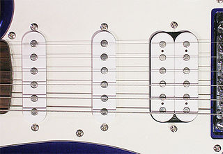
A pickup is a transducer that captures or senses mechanical vibrations produced by musical instruments, particularly stringed instruments such as the electric guitar, and converts these to an electrical signal that is amplified using an instrument amplifier to produce musical sounds through a loudspeaker in a speaker enclosure. The signal from a pickup can also be recorded directly.

A class-D amplifier or switching amplifier is an electronic amplifier in which the amplifying devices operate as electronic switches, and not as linear gain devices as in other amplifiers. They operate by rapidly switching back and forth between the supply rails, being fed by a modulator using pulse width, pulse density, or related techniques to encode the audio input into a pulse train. The audio escapes through a simple low-pass filter into the loudspeaker. The high-frequency pulses are blocked. Since the pairs of output transistors are never conducting at the same time, there is no other path for current flow apart from the low-pass filter/loudspeaker. For this reason, efficiency can exceed 90%.
This article illustrates some typical operational amplifier applications. A non-ideal operational amplifier's equivalent circuit has a finite input impedance, a non-zero output impedance, and a finite gain. A real op-amp has a number of non-ideal features as shown in the diagram, but here a simplified schematic notation is used, many details such as device selection and power supply connections are not shown. Operational amplifiers are optimised for use with negative feedback, and this article discusses only negative-feedback applications. When positive feedback is required, a comparator is usually more appropriate. See Comparator applications for further information.
In electronics, the Miller effect accounts for the increase in the equivalent input capacitance of an inverting voltage amplifier due to amplification of the effect of capacitance between the input and output terminals. The virtually increased input capacitance due to the Miller effect is given by
Parasitic capacitance is an unavoidable and usually unwanted capacitance that exists between the parts of an electronic component or circuit simply because of their proximity to each other. When two electrical conductors at different voltages are close together, the electric field between them causes electric charge to be stored on them; this effect is capacitance.
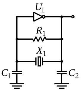
The Pierce oscillator is a type of electronic oscillator particularly well-suited for use in piezoelectric crystal oscillator circuits. Named for its inventor, George W. Pierce (1872–1956), the Pierce oscillator is a derivative of the Colpitts oscillator. Virtually all digital IC clock oscillators are of Pierce type, as the circuit can be implemented using a minimum of components: a single digital inverter, one resistor, two capacitors, and the quartz crystal, which acts as a highly selective filter element. The low manufacturing cost of this circuit and the outstanding frequency stability of the quartz crystal give it an advantage over other designs in many consumer electronics applications.
In electronics, a differentiator is a circuit that is designed such that the output of the circuit is approximately directly proportional to the rate of change of the input. A true differentiator cannot be physically realized, because it has infinite gain at infinite frequency. A similar effect can be achieved, however, by limiting the gain above some frequency. The differentiator circuit is essentially a high-pass filter.
An active differentiator includes some form of amplifier, while a passive differentiator is made only of resistors, capacitors and inductors.
In the field of electronics, a technique where part of the output of a system is used at startup can be described as bootstrapping.

A variety of types of electrical transformer are made for different purposes. Despite their design differences, the various types employ the same basic principle as discovered in 1831 by Michael Faraday, and share several key functional parts.
Parasitic oscillation is an undesirable electronic oscillation in an electronic or digital device. It is often caused by feedback in an amplifying device. The problem occurs notably in RF, audio, and other electronic amplifiers as well as in digital signal processing. It is one of the fundamental issues addressed by control theory.
The Miller theorem refers to the process of creating equivalent circuits. It asserts that a floating impedance element, supplied by two voltage sources connected in series, may be split into two grounded elements with corresponding impedances. There is also a dual Miller theorem with regards to impedance supplied by two current sources connected in parallel. The two versions are based on the two Kirchhoff's circuit laws.
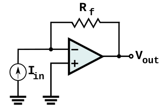
In electronics, a transimpedance amplifier (TIA) is a current to voltage converter, almost exclusively implemented with one or more operational amplifiers. The TIA can be used to amplify the current output of Geiger–Müller tubes, photo multiplier tubes, accelerometers, photo detectors and other types of sensors to a usable voltage. Current to voltage converters are used with sensors that have a current response that is more linear than the voltage response. This is the case with photodiodes where it is not uncommon for the current response to have better than 1% nonlinearity over a wide range of light input. The transimpedance amplifier presents a low impedance to the photodiode and isolates it from the output voltage of the operational amplifier. In its simplest form a transimpedance amplifier has just a large valued feedback resistor, Rf. The gain of the amplifer is set by this resistor and because the amplifier is in an inverting configuration, has a value of -Rf. There are several different configurations of transimpedance amplifiers, each suited to a particular application. The one factor they all have in common is the requirement to convert the low-level current of a sensor to a voltage. The gain, bandwidth, as well as current and voltage offsets change with different types of sensors, requiring different configurations of transimpedance amplifiers.
The operational amplifier integrator is an electronic integration circuit. Based on the operational amplifier (op-amp), it performs the mathematical operation of integration with respect to time; that is, its output voltage is proportional to the input voltage integrated over time.


