Circuit Scribe

Last updated

Circuit Scribe is a ball-point pen containing silver conductive ink one can use to draw circuits instantly on flexible substrates like paper. Circuit Scribe made its way onto Kickstarter (an online site where people can fund projects) on November 19, 2013, with its goal of raising $85,000 for the manufacturing of the first batch of pens. By December 31, 2013, Circuit Scribe was able to raise a total of $674,425 with 12,277 'backers' or donors. [1]

Contents

Similarly to drawing a picture, users can use a Circuit Scribe pen to draw lines on a simple piece of paper. They can then attach special electrical components on the drawn lines which allows the electrical currents to run through the components. This replaces the use of breadboards and wires.

Development

A team of researchers in Electroninks Incorporated, a startup company located at Research Park of the University of Illinois at Urbana-Champaign, created a water-based, non-toxic conductive ink that was noted as the Invention of the Month by Popular Science. [2] The team began by developing a prototype using pens from a different company and replacing the ink with their special silver ink. Once completed, they started a Kickstarter campaign to earn funding for a mass production of the final form of the pens.

Team

The researching team consists of S. Brett Walker, Jennifer A. Lewis, Michael Bell, Analisa Russo, and Nancy Beardsly. [3] Walker is the CEO of Electroninks and the co-founder along with Lewis, Bell, and the director of product development, Russo. Bell is also the chief operating officer while Beardsley is the technical support and user experience.

Prototype

The prototype pens are hand-cleaned Sakura Gelly Roll Metallic pens. The ink is replaced with the researchers' silver conductive ink. In order to have the right amount of ink flow to make smooth lines, the ink is precisely tuned.

Ink

The ink is created by placing an aqueous solution of silver nitrate into a flask of water combined with polyacrylic acid (PAA) and diethanolamine (DEA), the capping agent and reducing agent, respectively. After about twenty hours, the silver nitrate is dissolved, forming particles with a diameter of about 5 nanometers. In order to enlarge the size of the particle to an average diameter of about 400 nanometers, the flask is placed on a heated sonicator, a device that produces high-intensity ultrasound. Once cooled, the solution is poured into a larger flask and the thick precipitate, an insoluble solid which is formed is scraped out. From there, ethanol is added to coagulate the particles, or change the particles to a solid state. Most of the supernatant, the liquid lying above a layer of the precipitate, is then poured out so the remaining liquid can be centrifuged, or separated. After the process of centrifugation, the particles are placed back in water and forced through a syringe filter to remove unnecessary particles in the solution. Next, hydroxyethyl cellulose (HEC) is added as a binder and the entire mixture is homogenized. The solvents are allowed to evaporate until the ink has a desired viscosity or thickness. [2]

Once the ink is created, a roller ball pen is dismantled and cleaned so the ink can be placed inside using a flat tip spatula. After replacing the roller ball tip, a couple blasts of compressed air is shot from the back end to force the ink into the tip. The outer cover of the pen is replaced and the prototype of the Circuit Scribe is created. From there, the team launched its Kickstarter campaign.

Kickstarter Campaign

Circuit Scribe launched its campaign on Kickstarter to receive funding and included a list of pledges which people could donate a certain amount and get a corresponding gift: [1]

They also included stretch goals which include:

Modules

Circuit Scribe can be used to draw circuits that connect different types of modules, or individual components, such as: [4]

Power

Input

Connect

Output

Uses

The Circuit Scribe allows the user to draw electrical circuits in any shape with its silver ink. With this aspect and its ability to connect different types of modules, it is possible to produce simple designs like an Arduino, an open-source electronic platform based on hardware and software.

Arduino

Circuit Scribe allows users to create a paper Arduino (or a ‘paperduino’), which is demonstrated by the research team. The team first found the schematics on the Arduino website and modified them so that they would work on a pen plotter. [5] With a few modifications, they arranged the components and traces so that the board could be printed in a single layer. The alignments are set to 0.6 millimeters to match the width of the pen traces with a minimum distance of 0.1 millimeters. The pen plotter only prints lines and does not fill the patterns, so they designed large pads out of concentric circles and built up the pads for the components with some extra line features. This allows for a stronger conductivity. It is important to put chips close together to minimize the line resistance between them, but not so close that it is difficult to place the components. They used components from the 1206 package which are a bit larger than the original components from the Arduino. Before exporting the layout, they deselected every layer of the file except the top layer of traces. After exporting the file in .dxf format, both the wire width and the fill area options were deselected and the files were saved. Finally, the team measured the size of the board layout and dragged it onto a new sheet on Silhouette Studio. From there, the vertical height was adjusted to 2.945 inches and the speed was set to 1 in order to lay down the most ink when printed. The team went on to place components like resistors, capacitors, and LEDs on the printed silver ink. Components can be attached using tweezers and super glue, but can be reinforced using conductive epoxy.

Extras

Resistor Pen

As posted on their Kickstarter campaign, the creators of Circuit Scribe planned to develop resistor pens one can use to draw resistors the way one can use the Circuit Scribe to draw circuits. Although their stretch goal of $1,000,000 was not met by the deadline on the campaign, the team still managed to create them. [6]

Related Research Articles

<span class="mw-page-title-main">Ground (electricity)</span> Reference point in an electrical circuit from which voltages are measured

In electrical engineering, ground or earth may be a reference point in an electrical circuit from which voltages are measured, a common return path for electric current, or a direct physical connection to the Earth.

<span class="mw-page-title-main">Printed circuit board</span> Board to support and connect electronic components

A printed circuit board (PCB), also called printed wiring board (PWB), is a medium used to connect or "wire" components to one another in a circuit. It takes the form of a laminated sandwich structure of conductive and insulating layers: each of the conductive layers is designed with an artwork pattern of traces, planes and other features etched from one or more sheet layers of copper laminated onto and/or between sheet layers of a non-conductive substrate. Electrical components may be fixed to conductive pads on the outer layers in the shape designed to accept the component's terminals, generally by means of soldering, to both electrically connect and mechanically fasten them to it. Another manufacturing process adds vias: plated-through holes that allow interconnections between layers.

<span class="mw-page-title-main">Electrostatic discharge</span> Sudden flow of electric current between 2 electrically charged objects by contact

Electrostatic discharge (ESD) is a sudden and momentary flow of electric current between two electrically charged objects caused by contact, an electrical short or dielectric breakdown. A buildup of static electricity can be caused by tribocharging or by electrostatic induction. The ESD occurs when differently-charged objects are brought close together or when the dielectric between them breaks down, often creating a visible spark.

<span class="mw-page-title-main">Potentiometer</span> Type of resistor, usually with three terminals

A potentiometer is a three-terminal resistor with a sliding or rotating contact that forms an adjustable voltage divider. If only two terminals are used, one end and the wiper, it acts as a variable resistor or rheostat.

<span class="mw-page-title-main">Breadboard</span> Board with embedded spring clips that allows for electronics to be wired without soldering

A breadboard, solderless breadboard, or protoboard is a construction base used to build semi-permanent prototypes of electronic circuits. Unlike a perfboard or stripboard, breadboards do not require soldering or destruction of tracks and are hence reusable. For this reason, breadboards are also popular with students and in technological education.

In electronics and particularly computing, a jumper is a short length of conductor used to close, open or bypass part of an electronic circuit. They are typically used to set up or configure printed circuit boards, such as the motherboards of computers. The process of setting a jumper is often called strapping.

<span class="mw-page-title-main">Flexible electronics</span> Mounting of electronic devices on flexible plastic substrates

Flexible electronics, also known as flex circuits, is a technology for assembling electronic circuits by mounting electronic devices on flexible plastic substrates, such as polyimide, PEEK or transparent conductive polyester film. Additionally, flex circuits can be screen printed silver circuits on polyester. Flexible electronic assemblies may be manufactured using identical components used for rigid printed circuit boards, allowing the board to conform to a desired shape, or to flex during its use.

<span class="mw-page-title-main">Stripboard</span>

Stripboard is the generic name for a widely used type of electronics prototyping material for circuit boards characterized by a pre-formed 0.1 inches (2.54 mm) regular (rectangular) grid of holes, with wide parallel strips of copper cladding running in one direction all the way across one side of on an insulating bonded paper board. It is commonly also known by the name of the original product Veroboard, which is a trademark, in the UK, of British company Vero Technologies Ltd and Canadian company Pixel Print Ltd. It was originated and developed in the early 1960s by the Electronics Department of Vero Precision Engineering Ltd (VPE). It was introduced as a general-purpose material for use in constructing electronic circuits - differing from purpose-designed printed circuit boards (PCBs) in that a variety of electronics circuits may be constructed using a standard wiring board.

<span class="mw-page-title-main">Membrane keyboard</span> Type of computer keyboard with pressure pads instead of mechanical keys

A membrane keyboard is a computer keyboard whose "keys" are not separate, moving parts, as with the majority of other keyboards, but rather are pressure pads that have only outlines and symbols printed on a flat, flexible surface. Very little, if any, tactile feedback is felt when using such a keyboard.

An antifuse is an electrical device that performs the opposite function to a fuse. Whereas a fuse starts with a low resistance and is designed to permanently break an electrically conductive path, an antifuse starts with a high resistance, and programming it converts it into a permanent electrically conductive path. This technology has many applications.

<span class="mw-page-title-main">Laser trimming</span> Electronic circuit manufacturing method

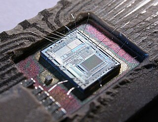
Laser trimming is the manufacturing process of using a laser to adjust the operating parameters of an electronic circuit.

A via is an electrical connection between two or more metal layers, and are commonly used in printed circuit boards. Essentially a via is a small drilled hole that goes through two or more adjacent layers; the hole is plated with metal that forms an electrical connection through the insulating layers.

<span class="mw-page-title-main">Antistatic device</span> Device that reduces or inhibits electrostatic discharge

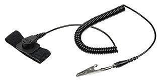
An antistatic device is any device that reduces, dampens, or otherwise inhibits electrostatic discharge, or ESD, which is the buildup or discharge of static electricity. ESD can damage electrical components such as computer hard drives, and even ignite flammable liquids and gases.

<span class="mw-page-title-main">Electronic circuit</span> Electrical circuit with active components

An electronic circuit is composed of individual electronic components, such as resistors, transistors, capacitors, inductors and diodes, connected by conductive wires or traces through which electric current can flow. It is a type of electrical circuit and to be referred to as electronic, rather than electrical, generally at least one active component must be present. The combination of components and wires allows various simple and complex operations to be performed: signals can be amplified, computations can be performed, and data can be moved from one place to another.

<span class="mw-page-title-main">E-textiles</span> Fabrics that incorporate electronic components

Electronic textiles or e-textiles are fabrics that enable electronic components such as batteries, lights, sensors, and microcontrollers to be embedded in them. They are not to be confused with smart textiles, which are fabrics that have been developed with new technologies that provide added value. Many smart clothing, wearable technology, and wearable computing projects involve the use of e-textiles.

<span class="mw-page-title-main">Thick-film technology</span>

Thick-film technology is used to produce electronic devices/modules such as surface mount devices modules, hybrid integrated circuits, heating elements, integrated passive devices and sensors. Main manufacturing technique is screen printing (stenciling), which in addition to use in manufacturing electronic devices can also be used for various graphic reproduction targets. It became one of the key manufacturing/miniaturisation techniques of electronic devices/modules during 1950s. Typical film thickness – manufactured with thick film manufacturing processes for electronic devices – is 0.0001 to 0.1 mm.

<span class="mw-page-title-main">Failure of electronic components</span> Ways electronic components fail and prevention measures

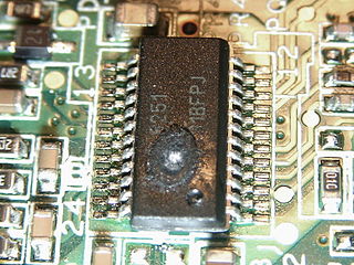
Electronic components have a wide range of failure modes. These can be classified in various ways, such as by time or cause. Failures can be caused by excess temperature, excess current or voltage, ionizing radiation, mechanical shock, stress or impact, and many other causes. In semiconductor devices, problems in the device package may cause failures due to contamination, mechanical stress of the device, or open or short circuits.

An electrically conductive adhesive is a glue that is primarily used for electronics.

<span class="mw-page-title-main">Co-fired ceramic</span> Integrated circuit package made out of fired ceramic material

Co-fired ceramic devices are monolithic, ceramic microelectronic devices where the entire ceramic support structure and any conductive, resistive, and dielectric materials are fired in a kiln at the same time. Typical devices include capacitors, inductors, resistors, transformers, and hybrid circuits. The technology is also used for robust assembly and packaging of electronic components multi-layer packaging in the electronics industry, such as military electronics, MEMS, microprocessor and RF applications.

<span class="mw-page-title-main">Makey Makey</span>

Makey Makey: An Invention Kit for Everyone is an invention kit designed to connect everyday objects to computer keys. Using a circuit board, alligator clips, and a USB cable, the toy uses closed loop electrical signals to send the computer either a keyboard stroke or mouse click signal. This function allows the Makey Makey to work with any computer program or webpage that accepts keyboard or mouse click.

References

  1. 1 2 "Circuit Scribe: Draw Circuits Instantly". Kickstarter. Kickstarter. Retrieved 28 October 2014.
  2. 1 2 "Invention of the Month: Conductive Ink". Popular Science. Bonnier Corporation Company.
  3. "The Team". Electroninks. Electroninks. Archived from the original on 2014-11-23. Retrieved 2014-11-13.
  4. "Circuit Scribe". 123D Circuits. Autodesk, Inc. Retrieved 29 October 2014.
  5. "Paperduino 2.0 with Circuit Scribe". Instructables. Autodesk, Inc.
  6. "Circuit Scribe: Draw Circuits Instantly". Kickstarter. Retrieved 2021-02-24.