Related Research Articles

A turbomolecular pump is a type of vacuum pump, superficially similar to a turbopump, used to obtain and maintain high vacuum. These pumps work on the principle that gas molecules can be given momentum in a desired direction by repeated collision with a moving solid surface. In a turbomolecular pump, a rapidly spinning fan rotor 'hits' gas molecules from the inlet of the pump towards the exhaust in order to create or maintain a vacuum.
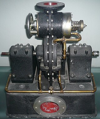
The Tesla turbine is a bladeless centripetal flow turbine invented by Nikola Tesla in 1913. It functions as nozzles apply a moving fluid to the edges of a set of discs. The engine uses smooth discs rotating in a chamber to generate rotational movement due to the momentum exchange between the fluid and the discs. The discs are arranged in an orientation similar to a stack of CDs on an axle.
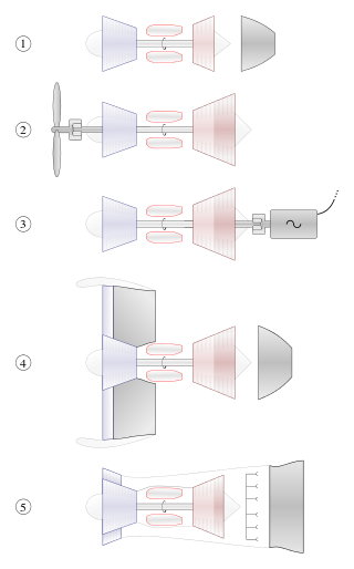
A gas turbine or gas turbine engine is a type of continuous flow internal combustion engine. The main parts common to all gas turbine engines form the power-producing part and are, in the direction of flow:

A turbofan or fanjet is a type of airbreathing jet engine that is widely used in aircraft propulsion. The word "turbofan" is a combination of references to the preceding generation engine technology of the turbojet and the additional fan stage. It consists of a gas turbine engine which achieves mechanical energy from combustion, and a ducted fan that uses the mechanical energy from the gas turbine to force air rearwards. Thus, whereas all the air taken in by a turbojet passes through the combustion chamber and turbines, in a turbofan some of that air bypasses these components. A turbofan thus can be thought of as a turbojet being used to drive a ducted fan, with both of these contributing to the thrust.
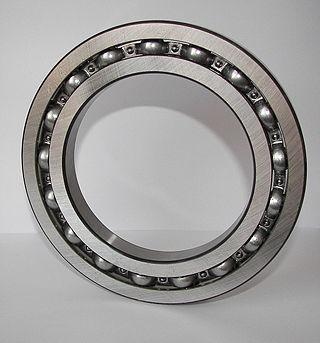
A bearing is a machine element that constrains relative motion to only the desired motion and reduces friction between moving parts. The design of the bearing may, for example, provide for free linear movement of the moving part or for free rotation around a fixed axis; or, it may prevent a motion by controlling the vectors of normal forces that bear on the moving parts. Most bearings facilitate the desired motion by minimizing friction. Bearings are classified broadly according to the type of operation, the motions allowed, or the directions of the loads (forces) applied to the parts.

Centrifugal compressors, sometimes called impeller compressors or radial compressors, are a sub-class of dynamic axisymmetric work-absorbing turbomachinery.

A compressor is a mechanical device that increases the pressure of a gas by reducing its volume. An air compressor is a specific type of gas compressor.

A magnetic bearing is a type of bearing that supports a load using magnetic levitation. Magnetic bearings support moving parts without physical contact. For instance, they are able to levitate a rotating shaft and permit relative motion with very low friction and no mechanical wear. Magnetic bearings support the highest speeds of any kind of bearing and have no maximum relative speed.
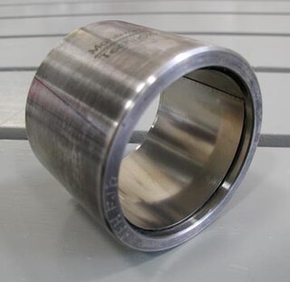
A foil bearing, also known as a foil-air bearing, is a type of air bearing. A shaft is supported by a compliant, spring-loaded foil journal lining. Once the shaft is spinning fast enough, the working fluid pushes the foil away from the shaft so that no contact occurs. The shaft and foil are separated by the air's high pressure, which is generated by the rotation that pulls gas into the bearing via viscosity effects. The high speed of the shaft with respect to the foil is required to initiate the air gap, and once this has been achieved, no wear occurs. Unlike aerostatic or hydrostatic bearings, foil bearings require no external pressurisation system for the working fluid, so the hydrodynamic bearing is self-starting.

A thrust bearing is a particular type of rotary bearing. Like other bearings they permanently rotate between parts, but they are designed to support a predominantly axial load.

An axial compressor is a gas compressor that can continuously pressurize gases. It is a rotating, airfoil-based compressor in which the gas or working fluid principally flows parallel to the axis of rotation, or axially. This differs from other rotating compressors such as centrifugal compressor, axi-centrifugal compressors and mixed-flow compressors where the fluid flow will include a "radial component" through the compressor.
A microturbine (MT) is a small gas turbine with similar cycles and components to a heavy gas turbine. The MT power-to-weight ratio is better than a heavy gas turbine because the reduction of turbine diameters causes an increase in shaft rotational speed. Heavy gas turbine generators are too large and too expensive for distributed power applications, so MTs are developed for small-scale power like electrical power generation alone or as combined cooling, heating, and power (CCHP) systems. The MT are 25 to 500 kW (34 to 671 hp) gas turbines evolved from piston engine turbochargers, aircraft auxiliary power units (APU) or small jet engines, the size of a refrigerator. Early turbines of 30–70 kW (40–94 hp) grew to 200–250 kW (270–340 hp).

Turbomachinery, in mechanical engineering, describes machines that transfer energy between a rotor and a fluid, including both turbines and compressors. While a turbine transfers energy from a fluid to a rotor, a compressor transfers energy from a rotor to a fluid. It is an important application of fluid mechanics.
A jet engine performs by converting fuel into thrust. How well it performs is an indication of what proportion of its fuel goes to waste. It transfers heat from burning fuel to air passing through the engine. In doing so it produces thrust work when propelling a vehicle but a lot of the fuel is wasted and only appears as heat. Propulsion engineers aim to minimize the degradation of fuel energy into unusable thermal energy. Increased emphasis on performance improvements for commercial airliners came in the 1970s from the rising cost of fuel.
Rotordynamics is a specialized branch of applied mechanics concerned with the behavior and diagnosis of rotating structures. It is commonly used to analyze the behavior of structures ranging from jet engines and steam turbines to auto engines and computer disk storage. At its most basic level, rotor dynamics is concerned with one or more mechanical structures (rotors) supported by bearings and influenced by internal phenomena that rotate around a single axis. The supporting structure is called a stator. As the speed of rotation increases the amplitude of vibration often passes through a maximum that is called a critical speed. This amplitude is commonly excited by imbalance of the rotating structure; everyday examples include engine balance and tire balance. If the amplitude of vibration at these critical speeds is excessive, then catastrophic failure occurs. In addition to this, turbomachinery often develop instabilities which are related to the internal makeup of turbomachinery, and which must be corrected. This is the chief concern of engineers who design large rotors.

A centrifugal fan is a mechanical device for moving air or other gases in a direction at an angle to the incoming fluid. Centrifugal fans often contain a ducted housing to direct outgoing air in a specific direction or across a heat sink; such a fan is also called a blower, blower fan, or squirrel-cage fan. Tiny ones used in computers are sometimes called biscuit blowers. These fans move air from the rotating inlet of the fan to an outlet. They are typically used in ducted applications to either draw air through ductwork/heat exchanger, or push air through similar impellers. Compared to standard axial fans, they can provide similar air movement from a smaller fan package, and overcome higher resistance in air streams.

A radial turbine is a turbine in which the flow of the working fluid is radial to the shaft. The difference between axial and radial turbines consists in the way the fluid flows through the components. Whereas for an axial turbine the rotor is 'impacted' by the fluid flow, for a radial turbine, the flow is smoothly oriented perpendicular to the rotation axis, and it drives the turbine in the same way water drives a watermill. The result is less mechanical stress which enables a radial turbine to be simpler, more robust, and more efficient when compared to axial turbines. When it comes to high power ranges the radial turbine is no longer competitive and the efficiency becomes similar to that of the axial turbines.
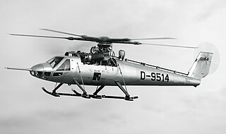
The Bölkow Bo 46 was a West German experimental helicopter built to test the Derschmidt rotor system that aimed to allow much higher speeds than traditional helicopter designs. Wind tunnel testing showed promise, but the Bo 46 demonstrated a number of problems and added complexity that led to the concept being abandoned. The Bo 46 was one of a number of new designs exploring high-speed helicopter flight that were built in the early 1960s.

The yaw system of wind turbines is the component responsible for the orientation of the wind turbine rotor towards the wind.
The yaw bearing is the most crucial and cost intensive component of a yaw system found on modern horizontal axis wind turbines. The yaw bearing must cope with enormous static and dynamic loads and moments during the wind turbine operation, and provide smooth rotation characteristics for the orientation of the nacelle under all weather conditions. It has also to be corrosion and wear resistant and extremely long lasting. It should last for the service life of the wind turbine) while being cost effective.
References
- 1 2 3 4 Chamis, Christos C. and Isaiah M. Blankson."Exo-Skeletal Engine – Novel Engine Concept". NASA, 2006. Retrieved: 5 May 2019
- 1 2 3 Roche, Joseph M., Donald T. Palac, James E. Hunter, David E. Myers, and Christopher A. Snyder. "Investigation of Exoskeletal Engine Propulsion System Concept". NASA, 2005. Retrieved: 31 August 2009