Non-nuclear device that creates an electromagnetic pulse
A cutaway view of a flux compression generator. The aluminum tube is detonated at the end extending out and beyond the copper-wire helix. On the other end a transformer enables the generator to work more efficiently into the electrical load.
EPFCGs are physically destroyed during operation, making them single-use. They require a starting current pulse to operate, usually supplied by capacitors.
At the start of the 1950s, the need for very short and powerful electrical pulses became evident to Soviet scientists conducting nuclear fusion research. The Marx generator, which stores energy in capacitors, was the only device capable at the time of producing such high power pulses. The prohibitive cost of the capacitors required to obtain the desired power motivated the search for a more economical device. The first magneto-explosive generators, which followed from the ideas of Andrei Sakharov, were designed to fill this role.[2][3]
Mechanics
For a constant intensity magnetic field of magnitude B traversing a surface S, the flux Φ is equal to B times S.
Magneto-explosive generators use a technique called "magnetic flux compression", described in detail below. The technique is made possible when the time scales over which the device operates are sufficiently brief that resistive current loss is negligible, and the magnetic flux through any surface surrounded by a conductor (copper wire, for example) remains constant, even though the size and shape of the surface may change.
This flux conservation can be demonstrated from Maxwell's equations. The most intuitive explanation of this conservation of enclosed flux follows from Lenz's law, which says that any change in the flux through an electric circuit will cause a current in the circuit which will oppose the change. For this reason, reducing the area of the surface enclosed by a closed loop conductor with a magnetic field passing through it, which would reduce the magnetic flux, results in the induction of current in the electrical conductor, which tends to keep the enclosed flux at its original value. In magneto-explosive generators, the reduction in area is accomplished by detonating explosives packed around a conductive tube or disk, so the resulting implosion compresses the tube or disk.[4] Since flux is equal to the magnitude of the magnetic field multiplied by the area of the surface, as the surface area shrinks the magnetic field strength inside the conductor increases. The compression process partially transforms the chemical energy of the explosives into the energy of an intense magnetic field surrounded by a correspondingly large electric current.
The purpose of the flux generator can be either the generation of an extremely strong magnetic field pulse, or an extremely strong electric current pulse; in the latter case the closed conductor is attached to an external electric circuit. This technique has been used to create the most intense manmade magnetic fields on Earth; fields up to about 1000teslas (about 1000 times the strength of a typical neodymium permanent magnet) can be created for a few microseconds.
Elementary description of flux compression
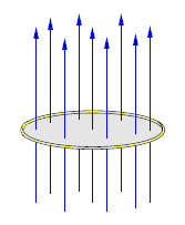
Fig. 1: Original magnetic field lines.
An external magnetic field (blue lines) threads a closed ring made of a perfect conductor (with zero resistance). The total magnetic flux through the ring is equal to the magnetic field multiplied by the area of the surface spanning the ring. The nine field lines represent the magnetic flux threading the ring.
Fig. 2: Configuration after the ring's diameter has been reduced.
Suppose the ring is deformed, reducing its cross-sectional area. The magnetic flux threading the ring, represented by five field lines, is reduced by the same ratio as the area of the ring. The variation of the magnetic flux induces a current (red arrows) in the ring by Faraday's law of induction, which in turn creates a new magnetic field circling the wire (green arrows) by Ampere's circuital law. The new magnetic field opposes the field outside the ring but adds to the field inside, so that the total flux in the interior of the ring is maintained: four green field lines added to the five blue lines give the original nine field lines.
Fig. 3: Magnetic field lines after compression.
By adding together the external magnetic field and the induced field, it can be shown that the net result is that the magnetic field lines originally threading the hole stay inside the hole, thus flux is conserved, and a current has been created in the conductive ring. The magnetic field lines are "pinched" closer together, so the (average) magnetic field intensity inside the ring increases by the ratio of the original area to the final area.
The various types of generators
The simple basic principle of flux compression can be applied in a variety of different ways. Soviet scientists at the VNIIEF in Sarov, pioneers in this domain, conceived of three different types of generators:[5][3][6]
In the first type of generator (MK-1, 1951) developed by Robert Lyudaev, the magnetic flux produced by a wound conductor is confined to the interior of a hollow metallic tube surrounded by explosives, and submitted to a violent compression when the explosives are fired; a device of the same type was developed in the United States a dozen years later by C. M. (Max) Fowler's team at Los Alamos.
In the second type of generator (MK-2, 1952), the magnetic flux, confined between the windings of the external conductor and a central conductive tube filled with explosive, is compressed by the conical 'piston' created by the deformation of the central tube as the detonation wave travels across the device.
A third type of generator (DEMG), developed by Vladimir Chernyshev, is cylindrical, and contains a stack of concave metallic disks, facing each other in pairs, to create hollow modules (with the number varying according to the desired power), and separated by explosives; each module functions as an independent generator.
Such generators can, if necessary, be utilised independently, or even assembled in a chain of successive stages: the energy produced by each generator is transferred to the next, which amplifies the pulse, and so on. For example, it is foreseen that the DEMG generator will be supplied by a MK-2 type generator.
Also, these can be either destructed just after an experiment, or used again and again while complying acceptable time to use.[7]
Hollow tube generators
In the spring of 1952, R. Z. Lyudaev, E. A. Feoktistova, G. A. Tsyrkov, and A. A. Chvileva undertook the first experiment with this type of generator, with the goal of obtaining a very high magnetic field.
Hollow tube generator.
The MK-1 generator functions as follows:
A longitudinal magnetic field is produced inside a hollow metallic conductor, by discharging a bank of capacitors into the solenoid that surrounds the cylinder. To ensure a rapid penetration of the field in the cylinder, there is a slit in the cylinder, which closes rapidly as the cylinder deforms;
The explosive charge placed around the tube is detonated in a manner that ensures that the compression of the cylinder commences when the current through the solenoid is at its maximum;
The convergent cylindrical shock wave unleashed by the explosion produces a rapid contraction (greater than 1km/s) of the central cylinder, compressing the magnetic field, and creating an inductive current, as per the explanation above (the speed of contraction permits, to first approximation, the neglect of Joule losses and the consideration of the cylinder as a perfect conductor).
The first experiments were able to attain magnetic fields of millions of gauss (hundreds of teslas), given an initial field of 30 kG (3 T) which is in the free space "air" the same as H = B/μ0 = (3 Vs/m2) / (4π × 10−7 Vs/Am) = 2.387×10⁶A/m (approximately 2.4 MA/m).
Helical generators
Helical generators were principally conceived to deliver an intense current to a load situated at a safe distance. They are frequently used as the first stage of a multi-stage generator, with the exit current used to generate a very intense magnetic field in a second generator.
Function of a helical generator.
The MK-2 generators function as follows:
A longitudinal magnetic field is produced in between a metallic conductor and a surrounding solenoid, by discharging a battery of capacitors into the solenoid;
After the charge is ignited, a detonation wave propagates in the explosive charge placed in the interior of the central metallic tube (from left to right on the figure);
Under the effect of the pressure of the detonation wave, the tube deforms and becomes a cone which contacts the helically wrapped coil, diminishing the number of turns not short-circuited, compressing the magnetic field and creating an inductive current;
At the point of maximal flux compression, the load switch is opened, which then delivers the maximal current to the load.
The MK-2 generator is particularly interesting for the production of intense currents, up to 108A (100 MA), as well as a very high energy magnetic field, as up to 20% of the explosive energy can be converted to magnetic energy, and the field strength can attain 2×10⁶gauss (200 T).
The practical realization of high performance MK-2 systems required the pursuit of fundamental studies by a large team of researchers; this was effectively achieved by 1956, following the production of the first MK-2 generator in 1952, and the achievement of currents over 100 megaamperes from 1953.
Disc generators
Disc generators
A DEMG generator functions as follows:
Conductive metallic discs, assembled in facing pairs to create hollow modules having the form of a lined torus, with explosive packed between pairs of modules, are stacked inside a cylinder;[8] the number of modules can vary according to the desired power (the figure shows a device of 15 modules), as well as the radius of the discs (of the order of 20 to 40cm).
Current runs through the device, supplied by a MK-2 generator, and an intense magnetic field is created inside each module.
When initiated, the explosion begins on the axis and propagates radially outwards, deforming the disc shaped protuberances with triangular section and pushing them away from the axis. The outward movement of this section of conductor plays the role of a piston.
As the explosion proceeds, the magnetic field is compressed in the inside of each module by the conductive piston and the simultaneous drawing together of the inner faces, also creating an inductive current.
As the induced current attains its maximum, the fuse opening switch fuses and the load switch simultaneously closes, allowing the current to be delivered to the load (the mechanism for the operation of the load switch is not explained in available documentation).
Systems using up to 25 modules have been developed at VNIIEF. Output of 100MJ at 256MA have been produced by a generator a metre in diameter composed of three modules.
↑ In practice, each prefabricated element, destined to be assembled into a cylinder, corresponds to an explosive device surrounded by two discs, which explains why the line of disks is terminated at each end by a hollow half module.
This page is based on this Wikipedia article Text is available under the CC BY-SA 4.0 license; additional terms may apply. Images, videos and audio are available under their respective licenses.