Levelling

Last updated
A wooden tripod holding an optical level is set up firmly on the ground. Tide station leveling.jpg
A wooden tripod holding an optical level is set up firmly on the ground.

Levelling or leveling (American English; see spelling differences) is a branch of surveying, the object of which is to establish or verify or measure the height of specified points relative to a datum. It is widely used in geodesy and cartography to measure vertical position with respect to a vertical datum, and in construction to measure height differences of construction artifacts.

Contents

Optical levelling

Stadia marks on a crosshair while viewing a metric levelling rod or staff. The top mark is at 1,500 mm and the lower is at 1,345 mm; the distance between those two marks is 155 mm, yielding a distance to the rod of 15.5 m. Baak.svg
Stadia marks on a crosshair while viewing a metric levelling rod or staff. The top mark is at 1,500 mm and the lower is at 1,345 mm; the distance between those two marks is 155 mm, yielding a distance to the rod of 15.5 m.

Optical levelling, also known as spirit levelling and differential levelling, employs an optical level , which consists of a precision telescope with crosshairs and stadia marks. The cross hairs are used to establish the level point on the target, and the stadia allow range-finding; stadia are usually at ratios of 100:1, in which case one metre between the stadia marks on the level staff (or rod) represents 100 metres from the target.

The complete unit is normally mounted on a tripod , and the telescope can freely rotate 360° in a horizontal plane. The surveyor adjusts the instrument's level by coarse adjustment of the tripod legs and fine adjustment using three precision levelling screws on the instrument to make the rotational plane horizontal. The surveyor does this with the use of a bull's eye level built into the instrument mount.

Procedure

Diagram showing relationship between two level staff, or rods, shown as 1 and 3. The level line of sight is 2. NivellementExample.svg
Diagram showing relationship between two level staff, or rods, shown as 1 and 3. The level line of sight is 2.

The surveyor looks through the eyepiece of telescope while an assistant holds a vertical level staff which is graduated in inches or centimeters. The level staff is placed vertically using a level, with its foot on the point for which the level measurement is required. The telescope is rotated and focused until the level staff is plainly visible in the crosshairs. In the case of a high accuracy manual level, the fine level adjustment is made by an altitude screw, using a high accuracy bubble level fixed to the telescope. This can be viewed by a mirror whilst adjusting or the ends of the bubble can be displayed within the telescope, which also allows assurance of the accurate level of the telescope whilst the sight is being taken. However, in the case of an automatic level, altitude adjustment is done automatically by a suspended prism due to gravity, as long as the coarse levelling is accurate within certain limits. When level, the staff graduation reading at the crosshairs is recorded, and an identifying mark or marker placed where the level staff rested on the object or position being surveyed.

A typical procedure for a linear track of levels from a known datum is as follows. Set up the instrument within 100 metres (110 yards) of a point of known or assumed elevation. A rod or staff is held vertical on that point and the instrument is used manually or automatically to read the rod scale. This gives the height of the instrument above the starting (backsight) point and allows the height of the instrument (H.I.) above the datum to be computed. The rod is then held on an unknown point and a reading is taken in the same manner, allowing the elevation of the new (foresight) point to be computed. The difference between these two readings equals the change in elevation, which is why this method is also called differential levelling. The procedure is repeated until the destination point is reached. It is usual practice to perform either a complete loop back to the starting point or else close the traverse on a second point whose elevation is already known. The closure check guards against blunders in the operation, and allows residual error to be distributed in the most likely manner among the stations.

Some instruments provide three crosshairs which allow stadia measurement of the foresight and backsight distances. These also allow use of the average of the three readings (3-wire leveling) as a check against blunders and for averaging out the error of interpolation between marks on the rod scale.

The two main types of levelling are single-levelling as already described, and double-levelling (double-rodding). In double-levelling, a surveyor takes two foresights and two backsights and makes sure the difference between the foresights and the difference between the backsights are equal, thereby reducing the amount of error. [1] Double-levelling costs twice as much as single-levelling. [2]

Turning a level

When using an optical level, the endpoint may be out of the effective range of the instrument. There may be obstructions or large changes of elevation between the endpoints. In these situations, extra setups are needed. Turning is a term used when referring to moving the level to take an elevation shot from a different location.

To "turn" the level, one must first take a reading and record the elevation of the point the rod is located on. While the rod is being kept in exactly the same location, the level is moved to a new location where the rod is still visible. A reading is taken from the new location of the level and the height difference is used to find the new elevation of the level gun. This is repeated until the series of measurements is completed.

The level must be horizontal to get a valid measurement. Because of this, if the horizontal crosshair of the instrument is lower than the base of the rod, the surveyor will not be able to sight the rod and get a reading. The rod can usually be raised up to 25 feet high, allowing the level to be set much higher than the base of the rod.

Trigonometric levelling

Archaeological survey using a Leica TPS1100 total station on an Iron Age dwelling in Ytterby, Sweden. GPS-matning pa jarnaldersboplats i Ytterby sn, Bohuslan, den 28 april 2006. Bild 1.JPG
Archaeological survey using a Leica TPS1100 total station on an Iron Age dwelling in Ytterby, Sweden.

The other standard method of levelling in construction and surveying is called trigonometric levelling, which is preferred when levelling "out" to a number of points from one stationary point. This is done by using a total station, or any other instrument to read the vertical, or zenith angle to the rod, and the change in elevation is calculated using trigonometric functions (see example below). At greater distances (typically 1,000 feet and greater), the curvature of the Earth, and the refraction of the instrument wave through the air must be taken into account in the measurements as well (see section below).

Formulation of trigonometric levelling Trigonometrisches Nivellement.jpg
Formulation of trigonometric levelling

Ex: an instrument at Point A reading to a rod at Point B a zenith angle of < 88°15'22" (degrees, minutes, seconds of arc) and a slope distance of 305.50 feet not factoring rod or instrument height would be calculated thus:

cos(88°15'22")(305.5)≈ 9.30 ft.,

meaning an elevation change of approximately 9.30 feet in elevation between Points A and B. So if Point A is at 1,000 feet of elevation, then Point B would be at approximately 1,009.30 feet of elevation, as the reference line (0°) for zenith angles is straight up going clockwise one complete revolution, and so an angle reading of less than 90 degrees (horizontal or flat) would be looking uphill and not down (and opposite for angles greater than 90 degrees), and so would gain elevation.

Refraction and curvature

The curvature of the earth means that a line of sight that is horizontal at the instrument will be higher and higher above a spheroid at greater distances. The effect may be insignificant for some work at distances under 100 meters. The increase in height of a straight line with distance D is:

where R is the radius of the earth.

The line of sight is horizontal at the instrument, but is not a straight line because of atmospheric refraction. The change of air density with elevation causes the line of sight to bend toward the earth.

The combined correction for refraction and curvature is approximately: [3]

or

For precise work these effects need to be calculated and corrections applied. For most work it is sufficient to keep the foresight and backsight distances approximately equal so that the refraction and curvature effects cancel out. Refraction is generally the greatest source of error in leveling. For short level lines the effects of temperature and pressure are generally insignificant, but the effect of the temperature gradient dT / dh can lead to errors. [4]

Levelling loops and gravity variations

Assuming error-free measurements, if the Earth's gravity field were completely regular and gravity constant, leveling loops would always close precisely:

around a loop. In the real gravity field of the Earth, this happens only approximately; on small loops typical of engineering projects, the loop closure is negligible, but on larger loops covering regions or continents it is not.

Instead of height differences, geopotential differences do close around loops:

where stands for gravity at the leveling interval i. For precise leveling networks on a national scale, the latter formula should always be used.

should be used in all computations, producing geopotential values for the benchmarks of the network.

High precision levelling, especially when conducted over long distances as used for the establishment and maintenance of vertical datums, is called geodetic levelling. [5]

Instruments

Classical instruments

The dumpy level was developed by English civil engineer William Gravatt, while surveying the route of a proposed railway line from London to Dover. More compact and hence both more robust and easier to transport, it is commonly believed that dumpy levelling is less accurate than other types of levelling, but such is not the case. Dumpy levelling requires shorter and therefore more numerous sights, but this fault is compensated by the practice of making foresights and backsights equal.

Precise level designs were often used for large leveling projects where utmost accuracy was required. They differ from other levels in having a very precise spirit level tube and a micrometer adjustment to raise or lower the line of sight so that the crosshair can be made to coincide with a line on the rod scale and no interpolation is required.

Automatic level

Automatic levels make use of a compensator that ensures that the line of sight remains horizontal once the operator has roughly leveled the instrument (to within maybe 0.05 degree). The compensator consists of small prisms suspended from wires inside of the level's chassis that are connected together in the shape of a pendulum. This allows for only horizontal light rays to enter, even in cases where the telescope of the instrument is not perfectly plumb. [6]

The surveyor sets the instrument up quickly and does not have to re-level it carefully each time they sight on a rod on another point. It also reduces the effect of minor settling of the tripod to the actual amount of motion instead of leveraging the tilt over the sight distance. Because the level of the instrument only needs to be adjusted once per setup, the surveyor can quickly and easily read as many side-shots as necessary between turns. Three level screws are used to level the instrument, as opposed to the four screws historically found in dumpy levels.

Laser level

Laser levels [7] project a beam which is visible and/or detectable by a sensor on the leveling rod. This style is widely used in construction work but not for more precise control work. An advantage is that one person can perform the levelling independently, whereas other types require one person at the instrument and one holding the rod.

The sensor can be mounted on earth-moving machinery to allow automated grading.

See also

Related Research Articles

<span class="mw-page-title-main">Geodesy</span> Science of measuring the shape, orientation, and gravity of the Earth and other astronomical bodies

Geodesy is the science of measuring and representing the geometry, gravity, and spatial orientation of the Earth in temporally varying 3D. It is called planetary geodesy when studying other astronomical bodies, such as planets or circumplanetary systems.

<span class="mw-page-title-main">Surveying</span> Science of determining the positions of points and the distances and angles between them

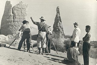
Surveying or land surveying is the technique, profession, art, and science of determining the terrestrial two-dimensional or three-dimensional positions of points and the distances and angles between them. These points are usually on the surface of the Earth, and they are often used to establish maps and boundaries for ownership, locations, such as the designed positions of structural components for construction or the surface location of subsurface features, or other purposes required by government or civil law, such as property sales.

<span class="mw-page-title-main">Theodolite</span> Optical surveying instrument

A theodolite is a precision optical instrument for measuring angles between designated visible points in the horizontal and vertical planes. The traditional use has been for land surveying, but it is also used extensively for building and infrastructure construction, and some specialized applications such as meteorology and rocket launching.

<span class="mw-page-title-main">Spirit level</span> Tool to indicate whether a surface is level or plumb

A spirit level, bubble level, or simply a level, is an instrument designed to indicate whether a surface is horizontal (level) or vertical (plumb). Two basic designs exist: tubular and bull's eye . Different types of spirit levels may be used by carpenters, stonemasons, bricklayers, other building trades workers, surveyors, millwrights and other metalworkers, and in some photographic or videographic work.

<span class="mw-page-title-main">Reticle</span> Aim markings in optical devices, e.g. crosshairs

A reticle, or reticule also known as a graticule, is a pattern of fine lines or markings built into the eyepiece of an optical device such as a telescopic sight, spotting scope, theodolite, optical microscope or the screen of an oscilloscope, to provide measurement references during visual inspections. Today, engraved lines or embedded fibers may be replaced by a digital image superimposed on a screen or eyepiece. Both terms may be used to describe any set of patterns used for aiding visual measurements and calibrations, but in modern use reticle is most commonly used for weapon sights, while graticule is more widely used for non-weapon measuring instruments such as oscilloscope display, astronomic telescopes, microscopes and slides, surveying instruments and other similar devices.

<span class="mw-page-title-main">Total station</span> Electro-optical instrument used in surveying and building construction

A total station or total station theodolite is an electronic/optical instrument used for surveying and building construction. It is an electronic transit theodolite integrated with electronic distance measurement (EDM) to measure both vertical and horizontal angles and the slope distance from the instrument to a particular point, and an on-board computer to collect data and perform triangulation calculations.
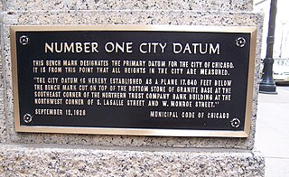
<span class="mw-page-title-main">Atmospheric refraction</span> Deviation of light as it moves through the atmosphere

Atmospheric refraction is the deviation of light or other electromagnetic wave from a straight line as it passes through the atmosphere due to the variation in air density as a function of height. This refraction is due to the velocity of light through air decreasing with increased density. Atmospheric refraction near the ground produces mirages. Such refraction can also raise or lower, or stretch or shorten, the images of distant objects without involving mirages. Turbulent air can make distant objects appear to twinkle or shimmer. The term also applies to the refraction of sound. Atmospheric refraction is considered in measuring the position of both celestial and terrestrial objects.

<span class="mw-page-title-main">Benchmark (surveying)</span> Point with known height used in surveying when levelling

The term benchmark, bench mark, or survey benchmark originates from the chiseled horizontal marks that surveyors made in stone structures, into which an angle iron could be placed to form a "bench" for a leveling rod, thus ensuring that a leveling rod could be accurately repositioned in the same place in the future. These marks were usually indicated with a chiseled arrow below the horizontal line. A benchmark is a type of survey marker.

<span class="mw-page-title-main">Level (optical instrument)</span> Optical instrument to verify horizontal points

A level is an optical instrument used to establish or verify points in the same horizontal plane in a process known as levelling. It is used in conjunction with a levelling staff to establish the relative height or levels of objects or marks. It is widely used in surveying and construction to measure height differences and to transfer, measure, and set heights of known objects or marks.

<span class="mw-page-title-main">Stadiametric rangefinding</span>

Stadiametric rangefinding, or the stadia method, is a technique of measuring distances with a telescopic instrument. The term stadia comes from a Greek unit of length Stadion which was the typical length of a sports stadium of the time. Stadiametric rangefinding is used for surveying and in the telescopic sights of firearms, artillery pieces, or tank guns, as well as some binoculars and other optics. It is still widely used in long-range military sniping, but in many professional applications it is being replaced with microwave, infrared, or laser rangefinding methods. Although much easier to use, electronic rangefinders can give away the shooter's position to a well-equipped adversary, and the need for accurate range estimation has existed for much longer than electronic rangefinders small and rugged enough to be suitable for military use.

<span class="mw-page-title-main">Meridian circle</span> Astronomical instrument for timing of the passage of stars

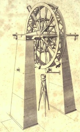
The meridian circle is an instrument for timing of the passage of stars across the local meridian, an event known as a culmination, while at the same time measuring their angular distance from the nadir. These are special purpose telescopes mounted so as to allow pointing only in the meridian, the great circle through the north point of the horizon, the north celestial pole, the zenith, the south point of the horizon, the south celestial pole, and the nadir. Meridian telescopes rely on the rotation of the sky to bring objects into their field of view and are mounted on a fixed, horizontal, east–west axis.

<span class="mw-page-title-main">Tacheometry</span> Archaic rapid surveying method

Tacheometry is a system of rapid surveying, by which the horizontal and vertical positions of points on the Earth's surface relative to one another are determined using a tacheometer without using a chain or tape, or a separate levelling instrument. Instead of the pole normally employed to mark a point, a staff similar to a level staff is used. This is marked with heights from the base or foot, and is graduated according to the form of tacheometer in use.

<span class="mw-page-title-main">Australian Height Datum</span> Vertical datum of Australia

The Australian Height Datum was introduced in 1971 as the official vertical datum for Australia, and thereby serves as the benchmark to which all height measurements are referred. The Australian Height Datum is an amalgamation of decades of spirit levelling work conducted by numerous state and territory authorities across the country, and was corrected to align with the mean sea level observations of thirty tide gauges positioned around the entire coastline. While it remains the published vertical datum for all surveying and engineering operations performed throughout Australia, newer technologies have uncovered numerous deficiencies, offsets and distortions within the Australian Height Datum, leading to discussions about defining a new Australian vertical datum.

<span class="mw-page-title-main">National Geodetic Vertical Datum of 1929</span> Vertical datum in the United States

The National Geodetic Vertical Datum of 1929 is the official name since 1973 of the vertical datum established for vertical control surveying in the United States of America by the General Adjustment of 1929. Originally known as Sea Level Datum of 1929, NGVD 29 was determined and published by the United States Coast and Geodetic Survey and used to measure the elevation of a point above and depression below mean sea level (MSL).

Stadia marks, also called stadia lines or stadia hairs, are crosshairs on the reticle of a theodolite or other surveying instrument that allow stadiametric rangefinding.

A level staff, also called levelling rod, is a graduated wooden or aluminium rod, used with a levelling instrument to determine the difference in height between points or heights of points above a vertical datum. When used for stadiametric rangefinding, the level staff is called a stadia rod.
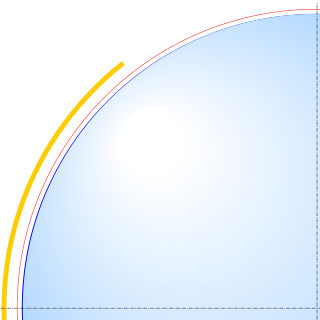
<span class="mw-page-title-main">Topographic Abney level</span> Surveying instrument

An Abney level and clinometer is an instrument used in surveying which consists of a fixed sighting tube, a movable spirit level that is connected to a pointing arm, and a protractor scale. An internal mirror allows the user to see the bubble in the level while sighting a distant target. It can be used as a hand-held instrument or mounted on a Jacob's staff for more precise measurement, and it is small enough to carry in a coat pocket.

<span class="mw-page-title-main">Vertical datum</span> Reference surface for vertical positions

In geodesy, surveying, hydrography and navigation, vertical datum or altimetric datum, is a reference coordinate surface used for vertical positions, such as the elevations of Earth-bound features and altitudes of satellite orbits and in aviation. In planetary science, vertical datums are also known as zero-elevation surface or zero-level reference.

This is a glossary of levelling terms. Levelling is a surveying method used to find relative height, one use of which is to ensure ground is level during construction, for example, when excavating to prepare for laying a foundation for a house.

Vertical position or vertical location is a position along a vertical direction above or below a given vertical datum . Vertical distance or vertical separation is the distance between two vertical positions. Many vertical coordinates exist for expressing vertical position: depth, height, altitude, elevation, etc. Points lying on an equigeopotential surface are said to be on the same vertical level, as in a water level.

References

  1. Ira Osborn Baker (1887). Leveling: Barometric, Trigonometric and Spirit. D. Van Nostrand. p.  126. single leveling.
  2. Guy Bomford (1980). Geodesy (4th ed.). Clarendon Press. p. 204. ISBN   0-19-851946-X.See: Geodesy .
  3. Davis, Foote, and Kelly, Surveying Theory and Practice, 1966 p. 152
  4. Guy Bomford (1980). Geodesy (4th ed.). Oxford: Clarendon Press. p. 222. ISBN   0-19-851946-X.See: Geodesy .
  5. United States. Department of Defense (1973). Glossary of Mapping, Charting, and Geodetic Terms. U.S. Government Printing Office. p. 98. Retrieved 2023-09-11.
  6. Ghilani, Charles (2010). Elementary Surveying: An Introduction to Geomatics (13th ed.). Pearson. pp. 90–91. ISBN   978-0-13-255434-3.
  7. John S. Scott (1992). Dictionary of Civil Engineering. Springer Science+Business Media. p. 252. ISBN   0-412-98421-0.