
The Quabbin Reservoir is the largest inland body of water in Massachusetts, and was built between 1930 and 1939. Along with the Wachusett Reservoir, it is the primary water supply for Boston, 65 miles (105 km) to the east, and 40 other cities and towns in Greater Boston. The Quabbin also supplies water to three towns west of the reservoir and acts as backup supply for three others. By 1989, it supplied water for 2.5 million people, about 40% of the state's population at the time. It has an aggregate capacity of 412 billion US gallons (1,560 GL) and an area of 38.6 square miles (99.9 km2).

The Massachusetts Water Resources Authority (MWRA) is a public authority in the Commonwealth of Massachusetts that provides wholesale drinking water and sewage services to certain municipalities and industrial users in the state, primarily in the Boston area.
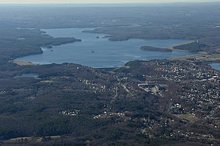
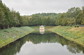
The Wachusett Reservoir is the second largest body of water in the state of Massachusetts. It is located in central Massachusetts, northeast of Worcester. It is part of the water supply system for metropolitan Boston maintained by the Massachusetts Water Resources Authority (MWRA). It has an aggregate capacity of 65 billion US gallons (250,000,000 m3) and an area of almost 7 square miles (18 km2). Water from the reservoir flows to the covered Norumbega Storage Facility via the Cosgrove Tunnel and the MetroWest Water Supply Tunnel. The reservoir has a maximum depth of 120 feet (37 m) and a mean depth of 48 feet (15 m).

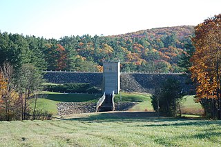
The Wachusett Dam in Clinton, Massachusetts, impounds the Nashua River, creating the Wachusett Reservoir. Construction started in 1897 and was completed in 1905. It is part of the Nashua River Watershed.

The Catskill Aqueduct, part of the New York City water supply system, brings water from the Catskill Mountains to Yonkers where it connects to other parts of the system.
The Quabbin Aqueduct carries water from the Quabbin Reservoir to the Wachusett Reservoir. It is part of the Eastern Massachusetts public water supply system, maintained by the Massachusetts Water Resources Authority (MWRA). At 25 miles (40 km) in length, it is one of the longest aqueduct tunnels in the world being 1⁄2 mile (0.80 km) shorter than the Hetch Hetchy Aqueduct.

The Ware River Diversion is a dam on the Ware River. It is part of the Boston, Massachusetts public water supply system, maintained by the Massachusetts Water Resources Authority (MWRA). It is located in Worcester County in the town of Barre, close to its border with Oakham.

The Ware River is a 35.4-mile-long (57.0 km) river in central Massachusetts. It has two forks, its West Branch, which begins in Hubbardston, Massachusetts, and its East Branch, which begins in Westminster, Massachusetts. The Ware River flows southwest through the middle of the state, joins the Quaboag River at Three Rivers, Massachusetts, to form the Chicopee River on its way to the Connecticut River.

The Wachusett Aqueduct is a secondary aqueduct that carries water from the Wachusett Reservoir to the John J. Carroll Water Treatment Plant at Walnut Hill in Marlborough, Massachusetts. It is part of the public water supply system for the communities of Greater Boston that are served by the Massachusetts Water Resources Authority (MWRA), which manages the aqueduct. The aqueduct serves as a standby backup to the Cosgrove Tunnel.

The Weston Reservoir is part of the greater Boston water supply maintained by the Massachusetts Water Resources Authority. It is located in central Weston, with its principal public access point on Ash Street.
The Barre Falls Dam is located on the Ware River in Barre, Massachusetts, about 0.3 miles (0.48 km) below the junction of the river's east and west branches and 13 miles (21 km) northwest of Worcester, Massachusetts.
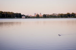
Chestnut Hill Reservoir is a reservoir created in 1870 on existing marshes and meadowland to supplement the city of Boston's water needs, located in its namesake neighborhood of Chestnut Hill. A 1.56 mile jogging loop abuts the reservoir. Chestnut Hill Reservoir was taken offline in 1978 as it was no longer needed for regular water supply distribution, but is maintained in emergency backup status. It is recognized today on the National Register of Historic Places and was designated as a Boston Landmark by the Boston Landmarks Commission in 1989.
The Cosgrove Aqueduct, also called the Cosgrove Tunnel, forms part of the water supply system for the communities of the Greater Boston area in eastern Massachusetts that are served by the Massachusetts Water Resources Authority. It is a man-made tunnel connecting the eastern end of the Wachusett Reservoir to the John J. Carroll Water Treatment Plant in Marlborough. From the treatment plant, water is delivered to the Boston area primarily by the MetroWest Water Supply Tunnel.
The Weston Aqueduct is an aqueduct operated by the Massachusetts Water Resources Authority (MWRA). Now part of the MWRA backup systems, it was designed to deliver water from the Sudbury Reservoir in Framingham to the Weston Reservoir in Weston. The 13.5-mile (21.7 km) aqueduct begins at the Sudbury Dam, and passes through the towns of Southborough, Framingham, Wayland, and Weston. In 1990, the route, buildings and bridges of the aqueduct were added to the National Register of Historic Places as the Weston Aqueduct Linear District.

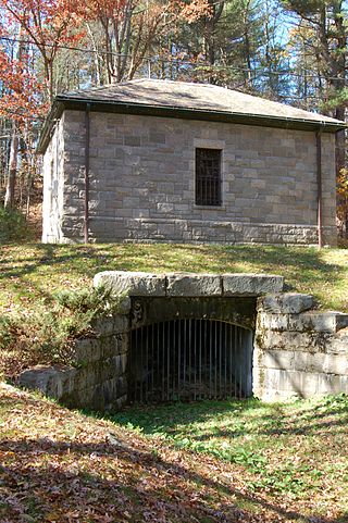
The Framingham Reservoir No. 1 Dam and Gatehouse is a historic water works facility in Framingham, Massachusetts. This complex is located at the end of Framingham Reservoir No. 1, which is also known as the Stearns Reservoir, off Winter Street and north of Long Avenue. Constructed from 1876 to 1878 as part of an expansion of the water supply of the city of Boston, this was designed by its first city architect George A. Clough. The historical purpose of the reservoir, which was located at the confluence of two branches of the Sudbury River, was primarily to control the river's water level, and secondarily to provide reserve supply capacity. The reservoir's reserve capacity was generally used only as a backup supply, as the reservoir's muddy bottom made it a less desirable source than reservoir No. 3 upstream. However the reservoir No. 1 system was nonetheless important due to its role in controlling the flow of the river downstream, and due to the gatehouse which controlled the water flows for all the Framingham reservoirs into the Sudbury Aqueduct. Reservoir No. 1 is no longer maintained as a reserve water source, although it is still owned by the Massachusetts Water Resources Authority, successor to the Boston Water Board which oversaw its construction. MWRA retains ownership as the gatehouse contains the connection between Reservoir No. 3 and the Sudbury Aqueudct which remain part of the emergency water systems.

The Sudbury Dam Historic District is a historic district on the southeastern end of Sudbury Reservoir off Massachusetts Route 30 in Framingham and Southborough, Massachusetts. The district encompasses the Sudbury Dam, which impounds the reservoir, and an area encompassing several historic structures located below the dam. The area includes water-supply-related structures from three phases of development of the Greater Boston water supply system. It was listed on the National Register of Historic Places in 1990.

The Sudbury Aqueduct is an aqueduct in Massachusetts. It runs for 16 miles (26 km) from Farm Pond at Waverly Street in Framingham to Chestnut Hill Reservoir in Boston’s Chestnut Hill neighborhood. A later built extension main runs from the Farm Pond gatehouse to the gatehouse at the Stearns Reservoir where additional mains connect to the Brackett and Foss Reservoirs Going east from Framingham, it runs through Sherborn before entering Natick. From Natick it runs east through Wellesley and Needham to the Charles River, which it crosses on the Echo Bridge into Newton. It ends at the Chestnut Hill Reservoir on the Newton side of the Newton-Boston line. The Massachusetts Water Resources Authority (MWRA) operates the aqueduct.
The Hultman Aqueduct forms part of the water supply system of eastern Massachusetts, managed by the Massachusetts Water Resources Authority (MWRA). The aqueduct extends from Southborough to Weston, connecting the Cosgrove Tunnel to the distribution network in the Greater Boston area. Opened in 1939, it replaced the Weston Aqueduct. It is now itself a secondary system, having been supplanted as the primary conduit in 2003 by the MetroWest Water Supply Tunnel. From 2009 to 2014, it was rehabilitated and taken offline, in order to repair leaks which were causing losses of at least 400,000 US gallons (1,500,000 L) of water per day in the 1990s.
The 2010 Boston water emergency occurred on May 1, 2010, when a water pipe in Weston, Massachusetts, broke and began flooding into the Charles River. This led to unsanitary water conditions in the greater Boston area, which resulted in Governor Deval Patrick declaring a state of emergency and an order for residents to boil drinking water. The leak was stopped on May 2. On May 4, the order was lifted. President Barack Obama signed an emergency disaster declaration offering federal help, authorizing the Department of Homeland Security and Federal Emergency Management Agency to coordinate disaster relief efforts with Massachusetts.

The John J. Carroll Water Treatment Plant (CWTP) is a water treatment plant operated since 2005 by the Massachusetts Water Resources Authority (MWRA) to treat water bound for Greater Boston. The plant is located at the town lines of Marlborough, Northborough, and Southborough, Massachusetts.

