Musgrave non-dead-centre engine

Last updated
Park Street Mill engine in the Bolton Steam Museum Musgrave Non-dead-centre Engine.jpg
Park Street Mill engine in the Bolton Steam Museum
View from above the Park Street Mill engine. Larger (low pressure) cylinder is on the left. Musgrave Non-dead-centre Engine, from above.jpg
View from above the Park Street Mill engine. Larger (low pressure) cylinder is on the left.

Musgrave's non-dead-centre engine was a stationary steam engine of unusual design, intended to solve the problem of stopping on dead centre. It was designed in 1887 to serve as a marine engine. It used a pair of linked cylinders to prevent the engine from stopping in a position where no turning force can be applied. At least one engine is known to survive.

Contents

Dead centres

The 'dead centre' of a piston engine with cranks is when the piston is at the exact top or bottom of the stroke and so the piston cannot exert any torque on the crankshaft. If a steam engine stops on dead centre, it will be unable to restart from that position.

Several solutions to this have been applied. One of the simplest is to try not to stop in this position, the crudest to apply a strong arm with a crowbar to turn the engine over a little. Small steam barring engines were also used to move the engine away from dead centre before starting. If the engine has multiple cylinders, most geometries for these are arranged so that all cylinders are never at dead centre together and so one may always be used for starting.

Musgrave's solution was more complex: using two cylinders, additional connecting rod linkages, and geometry to avoid the problem.

Dead centre is rarely a problem for internal combustion engines, as these usually require cranking over to provide cylinder compression and so do not attempt to self-start from stationary. Some large stationary diesel engines, where these used a compressed air starting mechanism, have suffered from the problem of dead centres and so used a small manual barring gear.

Geometry

In appearance, the engine resembles a 'parallel twin' with two vertical cylinders and a single crankshaft between them, but set perpendicular to the line of the cylinders and sharing a single crankpin.

A parallel twin with this many cylinders would be self-starting from dead centre anyway (assuming the usual crankshaft with cranks at 90°).

The geometry in operation is more like that of a vee-twin engine. The two cylinders work together, but with one leading the other by approx. 30°. The difference in this case is that the cylinders are no longer directly in line with the crankshaft and so use the connecting rod as a form of bellcrank. If one cylinder is at dead centre, the other will be away from it by the amount of this angle.

A vee-twin would offer all the advantages of the Musgrave engine, but would only need two simple connecting rods. The cylinders would no longer be parallel, but that is far from impractical to manufacture, as demonstrated by the even earlier diagonal engine.

Connecting rod

The two cylinders are connected to the single crankpin through a complex connecting rod of four separate links, and a rigid mounting point to the frame and cylinders. [1]

The main connecting rod is a large triangular frame, driven by both cylinders and driving the crankpin. Owing to the phase difference between the cylinders, this frame tilts back and forth as the engine rotates and so the cylinder crossheads drive it through two short connecting rods, allowing for some movement side-to-side. [2] A large rocking lever attached to the engine's frame holds the connecting rod roughly central. On the Bolton engine, this lever is extended past the frame and used to drive the condenser air pump.

Similarities to the Ross yoke

A similar mechanism appears to have been invented independently, much later on. This is the Ross yoke, invented by Andy Ross for use with Stirling engines. [3] A pair of parallel cylinders, one for the piston (driving), one containing the (driven) displacer, are connecting so that they drive back and forth with a suitable phase shift between them.

History

Marine engines

The design of the engine originated with W.Y. Fleming and P.Ferguson, marine engineers of Glasgow, in 1887. [1] It was intended for use as a marine engine, and at least 23 were supplied to ship builders requiring compact engines suitable for restricted space in engine rooms. [4]

Stationary engines

John Musgrave & Sons of the Globe Ironworks, Bolton was a mill engine builder, supplying the local cotton mills. He licensed the design in 1892, then patented further improvements to it in 1893. [1] [5]

Musgrave built up to 50 of these engines, the largest offering 1,500  ihp with quadruple expansion working. Ten of these quadruple expansion, four cylinder engines were built, the remainder mostly being two-cylinder compound engines, as the Park Street Mill engine. [1] The larger engines used Corliss valves. [6]

The non-dead-centre mechanism also evened-out power as the crank rotated, making it suitable for driving dynamos for electricity generation. The engine also had relative high speed for its day, making it possible to drive dynamos directly. A 500 hp Corliss valve engine was installed for electricity generation in Southport. [7]

A poster in the Science Museum advertises engines to "Fleming, Ferguson, & Dixon's patent". These are twin-cylinder compound engines with a single semi-rotary valve per cylinder (as for Park Street Mill) and are offered in a range from 8 to 250  ihp and with speeds from 160 to 250 rpm. [5] [8] Their working pressure is not specified, but the same poster also offers Lancashire boilers of up to 200  psi.

All of these engines are of robust construction, with large cast iron frames that have the cylinders cast integrally with them. The Park Street Mill engine is made from two large castings bolted together along a central plane and with the steam passages cored directly into the castings.

The crossheads are of the slipper pattern. This design has asymmetric bearing surfaces and so supports the forces better when the engine rotating in one direction than the other. They are commonly found on stationary engines that do not need to be reversed. However, in the Musgrave design, the two slideways face each other and so one of them will always be working "in reverse" to usual practice.

Patents

  • Fleming & Ferguson [9]
    • GB 2605   1887
    • GB 13843   1889
    • GB 20137   1890
    • GB 3165   1891
  • Musgrave & Dixon [9]
    • Improvements in Triple Expansion Engines, (1893). [10]

Surviving examples

Park Street Mill

Only one Musgrave non-dead-centre engine is known to survive, now preserved at the Bolton Steam Museum as part of the Northern Mill Engine Society collection. [11] [12] [13] On steam days these engines (or at least some) may be seen in action. The collection also includes two other engines built by Musgrave's, which are not non-dead-centre engines but much smaller barring engines.

Models

A small model of a twin-cylinder compound engine is on display. [5]
In 2009 the Model Engineer serialized the construction of a Musgrave engine, from castings supplied by the German firm of Lothar Matrian. [5]

Related Research Articles

Crankshaft Mechanism for converting reciprocating motion to rotation

A crankshaft is a shaft driven by a crank mechanism consisting of a series of cranks and crankpins to which the connecting rods of an engine is attached. It is a mechanical part able to perform a conversion between reciprocating motion and rotational motion. In a reciprocating engine, it translates reciprocating motion of the piston into rotational motion, whereas in a reciprocating compressor, it converts the rotational motion into reciprocating motion. In order to do the conversion between two motions, the crankshaft has "crank throws" or "crankpins", additional bearing surfaces whose axis is offset from that of the crank, to which the "big ends" of the connecting rods from each cylinder attach.

Crosshead

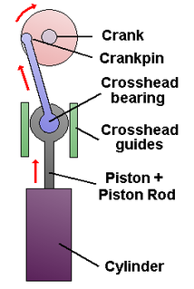
A crosshead is a mechanism used as part of the slider-crank linkages of long reciprocating engines and reciprocating compressors to eliminate sideways pressure on the piston. Also, the crosshead enables the connecting rod to freely move outside the cylinder. Because of the very small bore-to-stroke ratio on such engines, the connecting rod would hit the cylinder walls and block the engine from rotating if the piston was attached directly to the connecting rod like on trunk engines. Therefore, the longitudinal dimension of the crosshead must be matched to the stroke of the engine.

Valve gear Mechanism for controlling steam flow in a reciprocating steam engine.

The valve gear of a steam engine is the mechanism that operates the inlet and exhaust valves to admit steam into the cylinder and allow exhaust steam to escape, respectively, at the correct points in the cycle. It can also serve as a reversing gear. It is sometimes referred to as the "motion".

Connecting rod Piston engine component which connects the piston to the crankshaft

A connecting rod is the part of a piston engine which connects the piston to the crankshaft. Together with the crank, the connecting rod converts the reciprocating motion of the piston into the rotation of the crankshaft. The connecting rod is required to transmit the compressive and tensile forces from the piston. In its most common form, in an internal combustion engine, it allows pivoting on the piston end and rotation on the shaft end.

Compound steam engine Steam engine where steam is expanded in stages

A compound steam engine unit is a type of steam engine where steam is expanded in two or more stages. A typical arrangement for a compound engine is that the steam is first expanded in a high-pressure (HP) cylinder, then having given up heat and losing pressure, it exhausts directly into one or more larger-volume low-pressure (LP) cylinders. Multiple-expansion engines employ additional cylinders, of progressively lower pressure, to extract further energy from the steam.

Piston rod

In a piston engine, a piston rod joins a piston to the crosshead and thus to the connecting rod that drives the crankshaft or the driving wheels.

Engine balance refers to how the forces are balanced within an internal combustion engine or steam engine. The most commonly used terms are primary balance and secondary balance. First-order balance and second-order balance are also used. Unbalanced forces within the engine can lead to vibrations.

Reciprocating motion Repetitive back-and-forth linear motion

Reciprocating motion, also called reciprocation, is a repetitive up-and-down or back-and-forth linear motion. It is found in a wide range of mechanisms, including reciprocating engines and pumps. The two opposite motions that comprise a single reciprocation cycle are called strokes.

Crankpin Crankshaft section where connecting rods are attached

A crankpin is a mechanical device in an engine which connects the crankshaft to the connecting rod for each cylinder. It has a cylindrical surface, to allow the crankpin to rotate relative to the "big end" of the connecting rod.

Dead centre (engineering) The positions of an engines piston at the top or bottom of its stroke

In a reciprocating engine, the dead centre is the position of a piston in which it is either farthest from, or nearest to, the crankshaft. The former is known as Top Dead Centre (TDC) while the latter is known as Bottom Dead Centre (BDC).

Cyldon

Cyldon was the brand name for a range of model stationary steam engines, manufactured in Enfield, Middlesex, England between 1947 and 1951 by Sydney S Bird & Sons. The name Cyldon was an amalgamation of Sydney Bird's two son's names Cyril and Donald.

Marine steam engine Steam engine that is used to power a ship or boat

A marine steam engine is a steam engine that is used to power a ship or boat. This article deals mainly with marine steam engines of the reciprocating type, which were in use from the inception of the steamboat in the early 19th century to their last years of large-scale manufacture during World War II. Reciprocating steam engines were progressively replaced in marine applications during the 20th century by steam turbines and marine diesel engines.

A big bang engine is an unconventional engine designed so that some of the power strokes occur simultaneously or in close succession. This is achieved by changing the ignition timing, changing or re-timing the camshaft, and sometimes in combination with a change in crankpin angle. The goal is to change the power delivery characteristics of the engine. A regular firing multi-cylinder engine fires at approximately even intervals, giving a smooth-running engine. Because a big-bang engine has uneven power delivery, they tend to run rougher and generate more vibration than an even-firing engine.

Barring engine

A barring engine is a small engine that forms part of the installation of a large engine, and is used to turn the main engine to a favourable position from which it can be started. If the main engine has stopped close to its dead centre it is unable to restart itself. Barring may also be done to turn the engine over slowly (unloaded) for maintenance, or to prevent belt drives being left too long in one position and taking a "set".

Grasshopper beam engine

Grasshopper beam engines are beam engines that are pivoted at one end, rather than in the centre.

Return connecting rod engine

A return connecting rod, return piston rod or double piston rod engine or back-acting engine is a particular layout for a steam engine.

High-speed steam engine

High-speed steam engines were one of the final developments of the stationary steam engine. They ran at a high speed, of several hundred rpm, which was needed by tasks such as electricity generation.

Willans engine

The Willans engine or central valve engine was a high-speed stationary steam engine used mainly for electricity generation around the start of the 20th century.

Cyclone Waste Heat Engine

The Cyclone Waste Heat Engine (WHE) is a small steam engine developed to produce power from steam created from waste heat. It is an offshoot of the development of the Cyclone Mark V Engine by the company Cyclone Power Technologies of Pompano Beach, Florida. The original versions were designed by inventor Harry Schoell, founder of Cyclone Power Technologies and the later versions have been designed by the Ohio State University Center for Automotive Research (OSU-CAR).

Stuart Turner Ltd is a British engineering company, based in Henley-on-Thames, Oxfordshire, England, founded by engineer Sidney Marmaduke Stuart Turner in 1906.

References

  1. 1 2 3 4 Hills, Richard L. (1989). Power from Steam. Cambridge University Press. pp. 246–247. ISBN   0-521-45834-X.
  2. "Non-dead-centre engine in motion" (video). Northern Mill Engine Society.[ permanent dead link ]
  3. Andy Ross (inventor). "Stirling Engine with Ross yoke" (animated diagram).
  4. Watkins, George (1978). The steam engine in industry, Vol 1. Moorland Publishing. pp. 115, 117. ISBN   0-903485-65-6.
  5. 1 2 3 4 Konrad, Karl (April 2009). "Musgrave non-dead-centre engine". Model Engineer . 202 (4350).
  6. Nasmith, J. (1900). Cotton Mil Construction. (illustration shown in Hills, Power from Steam)
  7. Woodward, G. (May 1993). "History of a single-phase high-voltage distribution system". IEE Proceedings A. 140 (3): 207–214. doi:10.1049/ip-a-3.1993.0032.
  8. "Musgrave engines, Science Museum poster" (poster).
  9. 1 2 Hills, Power from Steam, ch.13 ref.27
  10. GB 189315395,Musgrave, James&Dixon, George,"Improvements in Triple Expansion Engines",published 1894-08-11, assigned to Globe Ironworks
  11. "NDC at Northern Mill Engine Society". Northern Mill Engine Society.
  12. "Northern Mill Engine Society". Northern Mill Engine Society.
  13. Pilling, Philip W. (1990). "Northern Mill Engine Society" (PDF). Archived from the original (PDF) on 2011-07-18. Retrieved 2009-07-04.