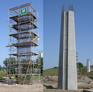
Reinforced concrete, also called ferroconcrete, is a composite material in which concrete's relatively low tensile strength and ductility are compensated for by the inclusion of reinforcement having higher tensile strength or ductility. The reinforcement is usually, though not necessarily, steel bars (rebar) and is usually embedded passively in the concrete before the concrete sets. However, post-tensioning is also employed as a technique to reinforce the concrete. In terms of volume used annually, it is one of the most common engineering materials. In corrosion engineering terms, when designed correctly, the alkalinity of the concrete protects the steel rebar from corrosion.

In continuum mechanics, stress is a physical quantity that describes forces present during deformation. For example, an object being pulled apart, such as a stretched elastic band, is subject to tensile stress and may undergo elongation. An object being pushed together, such as a crumpled sponge, is subject to compressive stress and may undergo shortening. The greater the force and the smaller the cross-sectional area of the body on which it acts, the greater the stress. Stress has dimension of force per area, with SI units of newtons per square meter (N/m2) or pascal (Pa).

In mechanics, compressive strength is the capacity of a material or structure to withstand loads tending to reduce size. In other words, compressive strength resists compression, whereas tensile strength resists tension. In the study of strength of materials, tensile strength, compressive strength, and shear strength can be analyzed independently.

A truss is an assembly of members such as beams, connected by nodes, that creates a rigid structure.
Stress–strain analysis is an engineering discipline that uses many methods to determine the stresses and strains in materials and structures subjected to forces. In continuum mechanics, stress is a physical quantity that expresses the internal forces that neighboring particles of a continuous material exert on each other, while strain is the measure of the deformation of the material.
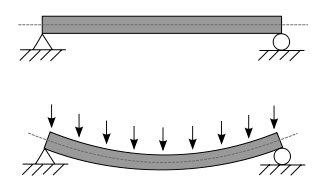
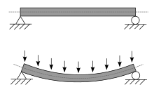
A beam is a structural element that primarily resists loads applied laterally across the beam's axis. Its mode of deflection is primarily by bending, as loads produce reaction forces at the beam's support points and internal bending moments, shear, stresses, strains, and deflections. Beams are characterized by their manner of support, profile, equilibrium conditions, length, and material.

In structural engineering, buckling is the sudden change in shape (deformation) of a structural component under load, such as the bowing of a column under compression or the wrinkling of a plate under shear. If a structure is subjected to a gradually increasing load, when the load reaches a critical level, a member may suddenly change shape and the structure and component is said to have buckled. Euler's critical load and Johnson's parabolic formula are used to determine the buckling stress of a column.

In applied mechanics, bending characterizes the behavior of a slender structural element subjected to an external load applied perpendicularly to a longitudinal axis of the element.
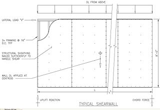
In structural engineering, a shear wall is a two-dimensional vertical element of a system that is designed to resist in-plane lateral forces, typically wind and seismic loads.

Euler–Bernoulli beam theory is a simplification of the linear theory of elasticity which provides a means of calculating the load-carrying and deflection characteristics of beams. It covers the case corresponding to small deflections of a beam that is subjected to lateral loads only. By ignoring the effects of shear deformation and rotatory inertia, it is thus a special case of Timoshenko–Ehrenfest beam theory. It was first enunciated circa 1750, but was not applied on a large scale until the development of the Eiffel Tower and the Ferris wheel in the late 19th century. Following these successful demonstrations, it quickly became a cornerstone of engineering and an enabler of the Second Industrial Revolution.

An I-beam is any of various structural members with an I or H-shaped cross-section. Technical terms for similar items include H-beam, w-beam, universal beam (UB), rolled steel joist (RSJ), or double-T. I-beams are typically made of structural steel and serve a wide variety of construction uses.

Henri Édouard Tresca was a French mechanical engineer, and a professor at the Conservatoire National des Arts et Métiers in Paris.

Plastic bending is a nonlinear behavior particular to members made of ductile materials that frequently achieve much greater ultimate bending strength than indicated by a linear elastic bending analysis. In both the plastic and elastic bending analyses of a straight beam, it is assumed that the strain distribution is linear about the neutral axis. In an elastic analysis this assumption leads to a linear stress distribution but in a plastic analysis the resulting stress distribution is nonlinear and is dependent on the beam's material.

Flexural strength, also known as modulus of rupture, or bend strength, or transverse rupture strength is a material property, defined as the stress in a material just before it yields in a flexure test. The transverse bending test is most frequently employed, in which a specimen having either a circular or rectangular cross-section is bent until fracture or yielding using a three-point flexural test technique. The flexural strength represents the highest stress experienced within the material at its moment of yield. It is measured in terms of stress, here given the symbol .

Bending is a manufacturing process that produces a V-shape, U-shape, or channel shape along a straight axis in ductile materials, most commonly sheet metal. Commonly used equipment include box and pan brakes, brake presses, and other specialized machine presses. Typical products that are made like this are boxes such as electrical enclosures and rectangular ductwork.
The neutral axis is an axis in the cross section of a beam or shaft along which there are no longitudinal stresses or strains.
Section modulus is a geometric property for a given cross-section used in the design of beams or flexural members. Other geometric properties used in design include area for tension and shear, radius of gyration for compression, and second moment of area and polar second moment of area for stiffness. Any relationship between these properties is highly dependent on the shape in question. Equations for the section moduli of common shapes are given below. There are two types of section moduli, the elastic section modulus and the plastic section modulus. The section moduli of different profiles can also be found as numerical values for common profiles in tables listing properties of such.

The focal mechanism of an earthquake describes the deformation in the source region that generates the seismic waves. In the case of a fault-related event, it refers to the orientation of the fault plane that slipped, and the slip vector and is also known as a fault-plane solution. Focal mechanisms are derived from a solution of the moment tensor for the earthquake, which itself is estimated by an analysis of observed seismic waveforms. The focal mechanism can be derived from observing the pattern of "first motions", whether the first arriving P waves break up or down. This method was used before waveforms were recorded and analysed digitally, and this method is still used for earthquakes too small for easy moment tensor solution. Focal mechanisms are now mainly derived using semi-automatic analysis of the recorded waveforms.

Structural engineering depends upon a detailed knowledge of loads, physics and materials to understand and predict how structures support and resist self-weight and imposed loads. To apply the knowledge successfully structural engineers will need a detailed knowledge of mathematics and of relevant empirical and theoretical design codes. They will also need to know about the corrosion resistance of the materials and structures, especially when those structures are exposed to the external environment.
In solid mechanics, pure bending is a condition of stress where a bending moment is applied to a beam without the simultaneous presence of axial, shear, or torsional forces. Pure bending occurs only under a constant bending moment since the shear force, which is equal to has to be equal to zero. In reality, a state of pure bending does not practically exist, because such a state needs an absolutely weightless member. The state of pure bending is an approximation made to derive formulas.