Three-phase electric power is a common type of alternating current used in electricity generation, transmission, and distribution. It is a type of polyphase system employing three wires and is the most common method used by electrical grids worldwide to transfer power.
In electrical engineering, the power factor of an AC power system is defined as the ratio of the real power absorbed by the load to the apparent power flowing in the circuit. Real power is the average of the instantaneous product of voltage and current and represents the capacity of the electricity for performing work. Apparent power is the product of RMS current and voltage. Due to energy stored in the load and returned to the source, or due to a non-linear load that distorts the wave shape of the current drawn from the source, the apparent power may be greater than the real power, so more current flows in the circuit than would be required to transfer real power alone. A power factor magnitude of less than one indicates the voltage and current are not in phase, reducing the average product of the two. A negative power factor occurs when the device generates real power, which then flows back towards the source.

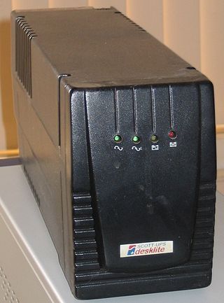
An uninterruptible power supply or uninterruptible power source (UPS) is an electrical apparatus that provides emergency power to a load when the input power source or mains power fails. A UPS differs from an auxiliary or emergency power system or standby generator in that it will provide near-instantaneous protection from input power interruptions, by supplying energy stored in batteries, supercapacitors, or flywheels. The on-battery run-time of most uninterruptible power sources is relatively short but sufficient to start a standby power source or properly shut down the protected equipment. It is a type of continual power system.

A rectifier is an electrical device that converts alternating current (AC), which periodically reverses direction, to direct current (DC), which flows in only one direction. The reverse operation is performed by an inverter.

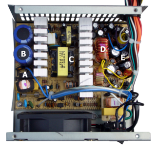
A power supply is an electrical device that supplies electric power to an electrical load. The main purpose of a power supply is to convert electric current from a source to the correct voltage, current, and frequency to power the load. As a result, power supplies are sometimes referred to as electric power converters. Some power supplies are separate standalone pieces of equipment, while others are built into the load appliances that they power. Examples of the latter include power supplies found in desktop computers and consumer electronics devices. Other functions that power supplies may perform include limiting the current drawn by the load to safe levels, shutting off the current in the event of an electrical fault, power conditioning to prevent electronic noise or voltage surges on the input from reaching the load, power-factor correction, and storing energy so it can continue to power the load in the event of a temporary interruption in the source power.

A power inverter, inverter or invertor is a power electronic device or circuitry that changes direct current (DC) to alternating current (AC). The resulting AC frequency obtained depends on the particular device employed. Inverters do the opposite of rectifiers which were originally large electromechanical devices converting AC to DC.

A switched-mode power supply is an electronic power supply that incorporates a switching regulator to convert electrical power efficiently.
In all fields of electrical engineering, power conversion is the process of converting electric energy from one form to another. A power converter is an electrical or electro-mechanical device for converting electrical energy. A power converter can convert alternating current (AC) into direct current (DC) and vice versa; change the voltage or frequency of the current or do some combination of these. The power converter can be as simple as a transformer or it can be a far more complex system, such as resonant converter. The term can also refer to a class of electrical machinery that is used to convert one frequency of alternating current into another. Power conversion systems often incorporate redundancy and voltage regulation.

Power electronics is the application of electronics to the control and conversion of electric power.

A rotary converter is a type of electrical machine which acts as a mechanical rectifier, inverter or frequency converter.

A traction substation, traction current converter plant, rectifier station or traction power substation (TPSS) is an electrical substation that converts electric power from the form provided by the electrical power industry for public utility service to an appropriate voltage, current type and frequency to supply railways, trams (streetcars) or trolleybuses with traction current.

Railway electrification systems using alternating current (AC) at 25 kilovolts (kV) are used worldwide, especially for high-speed rail. It is usually supplied at the standard utility frequency, which simplifies traction substations. The development of 25 kV AC electrification is closely connected with that of successfully using utility frequency.

Railway electrification using alternating current (AC) at 15 kilovolts (kV) and 16.7 hertz (Hz) are used on transport railways in Germany, Austria, Switzerland, Sweden, and Norway. The high voltage enables high power transmission with the lower frequency reducing the losses of the traction motors that were available at the beginning of the 20th century. Railway electrification in late 20th century tends to use 25 kV, 50 Hz AC systems which has become the preferred standard for new railway electrifications but extensions of the existing 15 kV networks are not completely unlikely. In particular, the Gotthard Base Tunnel still uses 15 kV, 16.7 Hz electrification.

A variable-frequency drive, variable-speed drives, AC drives, micro drives, inverter drives, or drives) is a type of AC motor drive that controls speed and torque by varying the frequency of the input electricity. Depending on its topology, it controls the associated voltage or current variation.

A frequency changer or frequency converter is an electronic or electromechanical device that converts alternating current (AC) of one frequency to alternating current of another frequency. The device may also change the voltage, but if it does, that is incidental to its principal purpose, since voltage conversion of alternating current is much easier to achieve than frequency conversion.
This is an alphabetical list of articles pertaining specifically to electrical and electronics engineering. For a thematic list, please see List of electrical engineering topics. For a broad overview of engineering, see List of engineering topics. For biographies, see List of engineers.

A rotary phase converter, abbreviated RPC, is an electrical machine that converts power from one polyphase system to another, converting through rotary motion. Typically, single-phase electric power is used to produce three-phase electric power locally to run three-phase loads in premises where only single-phase is available.
An induction heater is a key piece of equipment used in all forms of induction heating. Typically an induction heater operates at either medium frequency (MF) or radio frequency (RF) ranges.
An HVDC converter converts electric power from high voltage alternating current (AC) to high-voltage direct current (HVDC), or vice versa. HVDC is used as an alternative to AC for transmitting electrical energy over long distances or between AC power systems of different frequencies. HVDC converters capable of converting up to two gigawatts (GW) and with voltage ratings of up to 900 kilovolts (kV) have been built, and even higher ratings are technically feasible. A complete converter station may contain several such converters in series and/or parallel to achieve total system DC voltage ratings of up to 1,100 kV.
This glossary of electrical and electronics engineering is a list of definitions of terms and concepts related specifically to electrical engineering and electronics engineering. For terms related to engineering in general, see Glossary of engineering.


