Point-to-point construction

Last updated
Section of a typical Australian late 1930s radio, showing the point to point construction between components. Antique Radio Coils.jpg
Section of a typical Australian late 1930s radio, showing the point to point construction between components.

In electronics, point-to-point construction is a non-automated technique for constructing circuits which was widely used before the use of printed circuit boards (PCBs) and automated assembly gradually became widespread following their introduction in the 1950s. Circuits using thermionic valves (vacuum tubes) were relatively large, relatively simple (the number of large, hot, expensive devices which needed replacing was minimised), and used large sockets, all of which made the PCB less obviously advantageous than with later complex semiconductor circuits. Point-to-point construction is still widespread in power electronics, where components are bulky and serviceability is a consideration, and to construct prototype equipment with few or heavy electronic components. A common practice, especially in older point-to-point construction, is to use the leads of components such as resistors and capacitors to bridge as much of the distance between connections as possible, reducing the need to add additional wire between the components.

Contents

Before point-to-point connection, electrical assemblies used screws or wire nuts to hold wires to an insulating wooden or ceramic board. The resulting devices were prone to fail from corroded contacts, or mechanical loosening of the connections. Early premium marine radios, especially from Marconi, sometimes used welded copper in the bus-bar circuits, but this was expensive. The crucial invention was to apply soldering to electrical assembly. In soldering, an alloy of tin and lead (and/or other metals), known as solder, is melted and adheres to other, nonmolten metals, such as copper or tinned steel. Solder makes a strong electrical and mechanical connection.

Point-to-point wiring is not suitable for automated assembly (though see wire wrap, a similar method that is) and is carried out manually, making it both more expensive and more susceptible to wiring errors than PCBs, as connections are determined by the person doing assembly rather than by an etched circuit board. For production, rather than prototyping, errors can be minimised by carefully designed operating procedures.

An intermediate form of construction uses terminal strips (sometimes called "tag boards"), eyelet boards or turret boards. Note that if components are arranged on boards with tags, eyelets or turrets at both ends and wires going to the next components, then the construction is correctly called tag, eyelet or turret construction respectively, as the components are not going from point to point. Although cordwood construction can be wired in a similar way the density means that component placement is usually fixed by a substrate that components are inserted into.

Terminal strip construction

Point-to-point construction of military radio equipment Point to point construction.jpg
Point-to-point construction of military radio equipment
Underside of the chassis of a 1948 Motorola VT-71 7" television, showing the complexity of the point to point wiring. Motorolagoldenviewchassis.jpg
Underside of the chassis of a 1948 Motorola VT-71 7" television, showing the complexity of the point to point wiring.
Point to point wiring on a homemade tube amplifier circuit. Point to point wiring.jpg
Point to point wiring on a homemade tube amplifier circuit.

Terminal strip construction, which is often referred to as point-to-point construction within the tube guitar amplifier community, uses terminal strips (also called "tag boards"). A terminal strip has stamped tin-plated copper terminals, each with a hole through which wire ends could be pushed, fitted on an insulating strip, usually made of a cheap, heat-resistant material such as synthetic-resin bonded paper (FR-2), or bakelite reinforced with cotton. The insulator has an integral mounting bracket, sometimes electrically connected to one or more of the stamped loops to ground them to the chassis.

The chassis was constructed first, from sheet metal or wood. Insulated terminal strips were then riveted, nailed or screwed to the underside or interior of the chassis. Transformers, large capacitors, tube sockets and other large components were mounted to the top of the chassis. Their wires were led through holes to the underside or interior. The ends of lengths of wire or wire-ended components such as capacitors and resistors were pushed through the terminals, and usually looped and twisted. When all wires to be connected had been fitted to the terminal, they were soldered together (and to the terminal).

Professional electronics assemblers used to operate from books of photographs and follow an exact assembly sequence to ensure that they did not miss any components. This process is labor-intensive, subject to error and not suitable for automated production. Even after the introduction of printed circuit boards, it did not require laying out and manufacturing circuit boards.

Point-to-point and terminal strip construction continued to be used for some vacuum tube equipment even after the introduction of printed circuit boards. The heat of the tubes can degrade the circuit boards and cause them to become brittle and break. Circuit board degradation is often seen on inexpensive tube radios produced in the 1960s, especially around the hot output and rectifier tubes. American manufacturer Zenith continued to use point-to-point wiring in its tube-based television sets until the early 1970s.

Some audiophile equipment, such as amplifiers, continues to be point-to-point wired using terminal pins, [1] often in very small quantities. In this application modern point-to-point wiring is often used as a marketing design feature rather than a result of the economics of very-small-scale production.

Sometimes true point-to-point wiring—without terminal strips—with very short connections, is still used at very high radio frequencies (in the gigahertz range) to minimise stray capacitance and inductance; the capacitance between a circuit-board trace and some other conductor, and the inductance of a short track, become significant or dominant at high frequencies. In some cases careful PCB layout on a substrate with good high-frequency properties (e.g., ceramic) is sufficient. An example of this design is illustrated in an application note describing an avalanche transistor-based generator of pulses with risetime of a fraction of a nanosecond; the (few) critical components are connected directly to each other and to the output connector with the shortest possible leads. [2]

Particularly in complex equipment, wired circuits are often laid out as a "ladder" of side-by-side components, which need connecting to ladders or components by wire links. A good layout minimizes such links and wiring complexity, often approaching that of direct point-to-point. Amongst complex devices, the pre-PCB Tektronix vacuum-tube oscilloscopes stand out for their very well-designed point-to-point wiring. [3]

If parasitic effects are significant, point-to-point and terminal strip wiring have variable parasitic components, while the inductance and capacitance due to a PCB are the same for all samples and can be compensated for reliably which may be essential for some RF circuits. In some heavily optimised point-to-point RF constructions the circuit can be tuned by bending wires around.

Placing the completed unit in an enclosure protects the circuit from its environment, and users from electrical hazards.

A few large brand names still use terminal strip-type point-to-point boards, but usually for special product lines. Electric guitar amplifier manufacturer Marshall have reissued some of their older models, using this type of construction as a design feature, although their standard products have long used PCBs. Thermionic valve equipment usually does not have the valves mounted on the PCB in order to avoid heat damage, but instead use PCBs for the wiring, achieving the economy of mass-produced PCBs without the heat damage.

Breadboard

Prototypes which are subject to modification are often not made on PCBs, using instead breadboard construction. Historically this could be literally a breadboard, a wooden board with components attached to it and joined up with wire. More recently the term is applied to a board of thin insulating material with holes at standard 0.1-inch pitch; components are pushed through the holes to anchor them, and point-to-point wired on the other side of the board. A type of breadboard specifically for prototyping has this layout, but with strips of metal spring contacts beneath a grid of holes into which components are pushed to make electrical connections like any removable connector. Some portion of the terminals in a straight line in one direction are electrically connected, commonly in groups of 5-10 with multiple groups per row, these may be interspersed with columns that span the height of the board for the more common connections (typically the power supply rails). Such breadboards, and stripboards, fall somewhere between PCBs and point-to-point; they do not require design and manufacture of a PCB, and are as easily modified as a point-to-point setup.

Stripboard

A stripboard is a board with holes in square grid pattern, commonly with a 0.1-inch pitch; all the holes in a straight line are connected by a copper strip as on a PCB. Components are pushed through from the side without strips and soldered in place. The strips can be interrupted by scraping out a section of the copper, stripboard cutters are available for this task which are effectively a drill bit with a handle, they are used by rotating on the holes in a strip.

"Dead bug" construction

Free-form construction can be used in cases where a PCB would be too big or too much work to manufacture for a small number of components. Several methods of construction are used. At one extreme a wiring pen can be used with a perforated board, producing neat and professional results. At the other extreme is "dead bug" style, with the ICs flipped upside-down with their pins sticking up into the air like a dead insect, the leads of components are usually soldered directly to other components where possible, with many small circuits having no added wires. While it is messy-looking, free-form construction can be used to make more compact circuits than other methods. This is often used in BEAM robotics and in RF circuits where component leads must be kept short. This form of construction is used by amateurs for one-off circuits, and also professionally for circuit development, particularly at high frequencies. [4]

For high-frequency work, a grounded solderable metallic base such as the copper side of an unetched printed circuit board can be used as base and ground plane. Information on high-frequency breadboarding and illustrations of dead bug with ground plane construction are in a Linear Technologies application note. [4]

See also

Related Research Articles

<span class="mw-page-title-main">Wire</span> Single, usually cylindrical, flexible strand or bar or rod of metal

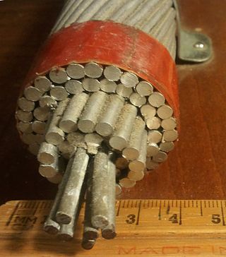
A wire is a flexible, round, bar of metal.

<span class="mw-page-title-main">Dual in-line package</span> Type of electronic component package

In microelectronics, a dual in-line package is an electronic component package with a rectangular housing and two parallel rows of electrical connecting pins. The package may be through-hole mounted to a printed circuit board (PCB) or inserted in a socket. The dual-inline format was invented by Don Forbes, Rex Rice and Bryant Rogers at Fairchild R&D in 1964, when the restricted number of leads available on circular transistor-style packages became a limitation in the use of integrated circuits. Increasingly complex circuits required more signal and power supply leads ; eventually microprocessors and similar complex devices required more leads than could be put on a DIP package, leading to development of higher-density chip carriers. Furthermore, square and rectangular packages made it easier to route printed-circuit traces beneath the packages.

In electrical engineering, a ground plane is an electrically conductive surface, usually connected to electrical ground.

<span class="mw-page-title-main">Wire wrap</span> Electronic component wiring technique

Wire wrap is an electronic component assembly technique that was invented to wire telephone crossbar switches, and later adapted to construct electronic circuit boards. Electronic components mounted on an insulating board are interconnected by lengths of insulated wire run between their terminals, with the connections made by wrapping several turns of uninsulated sections of the wire around a component lead or a socket pin.

<span class="mw-page-title-main">Printed circuit board</span> Board to support and connect electronic components

A printed circuit board (PCB), also called printed wiring board (PWB), is a medium used to connect or "wire" components to one another in a circuit. It takes the form of a laminated sandwich structure of conductive and insulating layers: each of the conductive layers is designed with a pattern of traces, planes and other features etched from one or more sheet layers of copper laminated onto and/or between sheet layers of a non-conductive substrate. Electrical components may be fixed to conductive pads on the outer layers in the shape designed to accept the component's terminals, generally by means of soldering, to both electrically connect and mechanically fasten them to it. Another manufacturing process adds vias, plated-through holes that allow interconnections between layers.

<span class="mw-page-title-main">Breadboard</span> Board with embedded spring clips that allows for electronics to be wired without soldering

A breadboard, solderless breadboard, or protoboard is a construction base used to build semi-permanent prototypes of electronic circuits. Unlike a perfboard or stripboard, breadboards do not require soldering or destruction of tracks and are hence reusable. For this reason, breadboards are also popular with students and in technological education.

<span class="mw-page-title-main">Electrical connector</span> Device used to join electrical conductors

Components of an electrical circuit are electrically connected if an electric current can run between them through an electrical conductor. An electrical connector is an electromechanical device used to create an electrical connection between parts of an electrical circuit, or between different electrical circuits, thereby joining them into a larger circuit.

<span class="mw-page-title-main">Surface-mount technology</span> Method for producing electronic circuits

Surface-mount technology (SMT), originally called planar mounting, is a method in which the electrical components are mounted directly onto the surface of a printed circuit board (PCB). An electrical component mounted in this manner is referred to as a surface-mount device (SMD). In industry, this approach has largely replaced the through-hole technology construction method of fitting components, in large part because SMT allows for increased manufacturing automation which reduces cost and improves quality. It also allows for more components to fit on a given area of substrate. Both technologies can be used on the same board, with the through-hole technology often used for components not suitable for surface mounting such as large transformers and heat-sinked power semiconductors.

<span class="mw-page-title-main">Stripboard</span>

Stripboard is the generic name for a widely used type of electronics prototyping material for circuit boards characterized by a pre-formed 0.1 inches (2.54 mm) regular (rectangular) grid of holes, with wide parallel strips of copper cladding running in one direction all the way across one side of on an insulating bonded paper board. It is commonly also known by the name of the original product Veroboard, which is a trademark, in the UK, of British company Vero Technologies Ltd and Canadian company Pixel Print Ltd. It was originated and developed in the early 1960s by the Electronics Department of Vero Precision Engineering Ltd (VPE). It was introduced as a general-purpose material for use in constructing electronic circuits - differing from purpose-designed printed circuit boards (PCBs) in that a variety of electronics circuits may be constructed using a standard wiring board.

<span class="mw-page-title-main">Through-hole technology</span> Circuit board manufacturing technique

In electronics, through-hole technology is a manufacturing scheme in which leads on the components are inserted through holes drilled in printed circuit boards (PCB) and soldered to pads on the opposite side, either by manual assembly or by the use of automated insertion mount machines.

<span class="mw-page-title-main">Hybrid integrated circuit</span> Type of miniature electronic circuit

A hybrid integrated circuit (HIC), hybrid microcircuit, hybrid circuit or simply hybrid is a miniaturized electronic circuit constructed of individual devices, such as semiconductor devices and passive components, bonded to a substrate or printed circuit board (PCB). A PCB having components on a Printed Wiring Board (PWB) is not considered a true hybrid circuit according to the definition of MIL-PRF-38534.

A via is an electrical connection between two or more metal layers, and are commonly used in printed circuit boards (PCB). Essentially a via is a small drilled hole that goes through two or more adjacent layers; the hole is plated with metal that forms an electrical connection through the insulating layers.

<span class="mw-page-title-main">Electronic kit</span>

An electronic kit is a package of electrical components used to build an electronic device. Generally, kits are composed of electronic components, a circuit diagram (schematic), assembly instructions, and often a printed circuit board (PCB) or another type of prototyping board.

<span class="mw-page-title-main">Perfboard</span> Material for prototyping electronic circuits

Perfboard is a material for prototyping electronic circuits. It is a thin, rigid sheet with holes pre-drilled at standard intervals across a grid, usually a square grid of 0.1 inches (2.54 mm) spacing. These holes are ringed by round or square copper pads, though bare boards are also available. Inexpensive perfboard may have pads on only one side of the board, while better quality perfboard can have pads on both sides. Since each pad is electrically isolated, the builder makes all connections with either wire wrap or miniature point to point wiring techniques. Discrete components are soldered to the prototype board such as resistors, capacitors, and integrated circuits. The substrate is typically made of paper laminated with phenolic resin or a fiberglass-reinforced epoxy laminate (FR-4).

<span class="mw-page-title-main">Turret board</span> Early electronic circuit board design

In electronics, turret boards were an early attempt at making circuits that were relatively rugged, producible, and serviceable in the days before printed circuit boards (PCBs). As this method was somewhat more expensive than conventional "point-to-point" wiring techniques, it was generally found in the more expensive components, such as professional, commercial, and military audio and test equipment. This is similar to cordwood construction.

<span class="mw-page-title-main">Electronic circuit</span> Electrical circuit with active components

An electronic circuit is composed of individual electronic components, such as resistors, transistors, capacitors, inductors and diodes, connected by conductive wires or traces through which electric current can flow. It is a type of electrical circuit. For a circuit to be referred to as electronic, rather than electrical, generally at least one active component must be present. The combination of components and wires allows various simple and complex operations to be performed: signals can be amplified, computations can be performed, and data can be moved from one place to another.

<span class="mw-page-title-main">Screw terminal block</span> Device for electrical wire connection

A screw terminal is a type of electrical connection where a wire is held by the tightening of a screw.

<span class="mw-page-title-main">Jump wire</span> Electrical wire connecting circuit components without soldering

A jump wire is an electrical wire, or group of them in a cable, with a connector or pin at each end, which is normally used to interconnect the components of a breadboard or other prototype or test circuit, internally or with other equipment or components, without soldering.
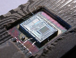
<span class="mw-page-title-main">Soldering</span> Process of joining metal pieces with heated filler metal

Soldering is a process of joining two metal surfaces together using a filler metal called solder. The soldering process involves heating the surfaces to be joined and melting the solder, which is then allowed to cool and solidify, creating a strong and durable joint.

<span class="mw-page-title-main">Electronics prototyping</span>

In electronics, prototyping means building an actual circuit to a theoretical design to verify that it works, and to provide a physical platform for debugging it if it does not. The prototype is often constructed using techniques such as wire wrapping or using a breadboard, stripboard or perfboard, with the result being a circuit that is electrically identical to the design but not physically identical to the final product.

References

  1. musicradar.com
  2. Linear Technology AN47 - High Speed Amplifier Techniques, p.AN47-94, figure D3, head of avalanche pulse generator. "Lead lengths ... should be experimented with to get best output pulse purity."
  3. Illustration of interior of Tektronix 310A oscilloscope, with complex point-to-point wiring using ceramic, rather than bonded-paper, terminal strips.
  4. 1 2 Linear Technology (August 1991). "Application Note 47: High Speed Amplifier Techniques" (pdf). Retrieved 2016-02-14., describes and illustrates dead-bug breadboards with ground plane, and other prototyping techniques. Illustrated in Figures F1 to F24, from p.AN47-98. Information on breadboarding on pages AN47-26 to AN47-29.