Rigid-frame bridge

Last updated
Concrete Rigid-Frame Bridge, United States Bridge MerrittPkwy.jpg
Concrete Rigid-Frame Bridge, United States

A Rigid-frame bridge is a bridge in which the superstructure and substructure are rigidly connected to act as a continuous unit. Typically, the structure is cast monolithically, making the structure continuous from deck to foundation. The connections between members are rigid connections which transfer bending moment, axial forces, and shear forces. A bridge design consisting of a rigid frame can provide significant structural benefits, but can also be difficult to design and/or construct.

Contents

History

The use of rigid-frame bridges began in Germany in the early twentieth century and quickly spread to the Americas. Emílio Henrique Baumgart and Arthur G. Hayden, in particular, gained notoriety for their use of concrete rigid frames in the early 1920s. [1] :149 At the time, reinforced concrete was commonly used in bridge design [2] but the superstructure was designed with bearings on the substructure. [1] :149 In concrete rigid-frame design, there are no bearings. Instead the superstructure is cast monolithically with the substructure and the entire bridge from deck to footing is continuous.

Engineers have found this type of design advantageous for many reasons. Moments at the center of the deck of a rigid-frame bridge are smaller than the corresponding moments in a simply supported deck. [3] Therefore, a much shallower cross section at mid-span can be used. [3] Additional benefits are that less space is required for the approaches and structural details for where the deck bears on the abutments are not necessary. [3] Engineers have also noted some disadvantages of rigid frame bridges. The placement of steel reinforcing bars (rebars) can be very difficult and the forming/placement of the concrete is complicated. [1] :153 Furthermore, rigid frames are statically indeterminate and the analysis is more challenging than that of simply supported structures.

Types of rigid-frame bridge

Single span

Single span rigid-frame bridges are typically made of reinforced concrete and are commonly used on parkways and other roadways. [4] This design is an efficient use of material as the cross section at mid-span is relatively narrow and the amount of concrete needed at the abutments is reduced. [4] The narrow section at mid-span gives the bridge profile a slight arch shape making this design particularly useful when large headroom is required. The profile also makes the bridge more architecturally pleasing than a beam bridge. Rigid-frame design may be the most efficient bridge type for spans between 35 and 80 feet (11 and 24 m). [5] If steel is used, the economic advantage extends to spans of 120 feet (37 m). [5]

V-shaped

A v-shaped rigid frame is an efficient way to support a longer bridge where using only one span isn't feasible. Each v-shaped pier supports the deck in two places while only requiring one foundation. The bending moments experienced in the piers are minimal, allowing significant reductions in the foundation size. [6] Additionally, the effective length of each span is shortened compared to the spans of a bridge with vertical piers. [7] However, this system is less commonly used in rigid frame bridges because the piers need to be approximately centered under the bridge. Often the bridges span over roadways or waterways and construction of piers in those cases can be costly and challenging.[ citation needed ]

Batter-post

Diagram of a batter-post rigid frame bridge Rigid frame bridge.png
Diagram of a batter-post rigid frame bridge

Batter-post rigid frame bridges are defined by their supports that run from the deck to the abutments at an angle. This design supports the deck in a similar way to v-shaped piers but differs in how the foundations must be built. The piers bear on or next to the abutments, eliminating the need for foundations directly beneath the bridge. This is particularly advantageous when the bridge crosses a river and constructing a foundation in the water is challenging. [8] As a result, either the abutments have to be made larger or additional foundations must be placed next to the abutments.

Recent advances

In the past few years, most research on rigid frame bridges is related to retrofitting existing structures to meet new seismic specifications. [9] This research often finds that the amount of reinforcing required at beam-to-column joints needs to be increased in concrete structures. In many bridges, the amount of steel required by the seismic code causes congestion at the joints. [9] To alleviate this, steel fibers can be used as reinforcement to improve the bond between the rebars and the surrounding concrete. [9] Tests have shown that by using steel fiber reinforced concrete, the anchorage length of rebar can be reduced while improving shear and flexural capacities. [9] The reduced anchorage length required reduces the congestion at beam-to-column joints.

Another advancement is in the use of prestressed concrete. Prestressed concrete is a major advance in concrete engineering and has effectively been used in rigid frame bridge construction. [10] This is notable because it was already challenging to place standard reinforcing in a concrete rigid frame bridge. Prestressing the rebars is more difficult but was proven to still be feasible. [10] Prestressed concrete is useful in bridge construction because it has higher tensile strength than traditional reinforced concrete, allowing for longer bridge spans.

Related Research Articles

<span class="mw-page-title-main">Reinforced concrete</span> Concrete with rebar

Reinforced concrete, also called ferroconcrete, is a composite material in which concrete's relatively low tensile strength and ductility are compensated for by the inclusion of reinforcement having higher tensile strength or ductility. The reinforcement is usually, though not necessarily, steel bars (rebar) and is usually embedded passively in the concrete before the concrete sets. However, post-tensioning is also employed as a technique to reinforce the concrete. In terms of volume used annually, it is one of the most common engineering materials. In corrosion engineering terms, when designed correctly, the alkalinity of the concrete protects the steel rebar from corrosion.

<span class="mw-page-title-main">Rebar</span> Steel reinforcement

Rebar, known when massed as reinforcing steel or reinforcement steel, is a steel bar used as a tension device in reinforced concrete and reinforced masonry structures to strengthen and aid the concrete under tension. Concrete is strong under compression, but has low tensile strength. Rebar significantly increases the tensile strength of the structure. Rebar's surface features a continuous series of ribs, lugs or indentations to promote a better bond with the concrete and reduce the risk of slippage.

<span class="mw-page-title-main">Arch bridge</span> Bridge with arch-shaped supports

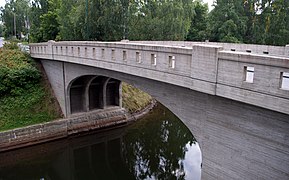
An arch bridge is a bridge with abutments at each end shaped as a curved arch. Arch bridges work by transferring the weight of the bridge and its loads partially into a horizontal thrust restrained by the abutments at either side. A viaduct may be made from a series of arches, although other more economical structures are typically used today.

<span class="mw-page-title-main">Seismic retrofit</span> Modification of existing structures to make them more resistant to seismic activity

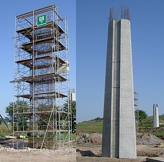
Seismic retrofitting is the modification of existing structures to make them more resistant to seismic activity, ground motion, or soil failure due to earthquakes. With better understanding of seismic demand on structures and with recent experiences with large earthquakes near urban centers, the need of seismic retrofitting is well acknowledged. Prior to the introduction of modern seismic codes in the late 1960s for developed countries and late 1970s for many other parts of the world, many structures were designed without adequate detailing and reinforcement for seismic protection. In view of the imminent problem, various research work has been carried out. State-of-the-art technical guidelines for seismic assessment, retrofit and rehabilitation have been published around the world – such as the ASCE-SEI 41 and the New Zealand Society for Earthquake Engineering (NZSEE)'s guidelines. These codes must be regularly updated; the 1994 Northridge earthquake brought to light the brittleness of welded steel frames, for example.

<span class="mw-page-title-main">Beam bridge</span> Type of bridge

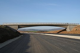
Beam bridges are the simplest structural forms for bridge spans supported by an abutment or pier at each end. No moments are transferred throughout the support, hence their structural type is known as simply supported.

<span class="mw-page-title-main">Plate girder bridge</span> Type of bridge

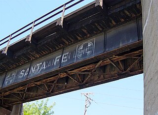
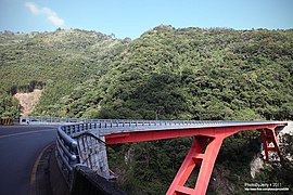
A plate girder bridge is a bridge supported by two or more plate girders.

<span class="mw-page-title-main">Abutment</span> Substructure at the ends of a bridge span or dam supporting its superstructure

An abutment is the substructure at the ends of a bridge span or dam supporting its superstructure. Single-span bridges have abutments at each end that provide vertical and lateral support for the span, as well as acting as retaining walls to resist lateral movement of the earthen fill of the bridge approach. Multi-span bridges require piers to support ends of spans unsupported by abutments. Dam abutments are generally the sides of a valley or gorge, but may be artificial in order to support arch dams such as Kurobe Dam in Japan.

<span class="mw-page-title-main">Tied-arch bridge</span>

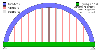
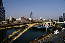
A tied-arch bridge is an arch bridge in which the outward horizontal forces of the arch(es) caused by tension at the arch ends to a foundation are countered by equal tension of its own gravity plus any element of the total deck structure such great arch(es) support. The arch(es) have strengthened chord(s) that run to a strong part of the deck structure or to independent tie-rods below the arch ends.

<span class="mw-page-title-main">Girder bridge</span> Bridge built of girders placed on bridge abutments and foundation piers

A girder bridge is a bridge that uses girders as the means of supporting its deck. The two most common types of modern steel girder bridges are plate and box.

<span class="mw-page-title-main">Hydrodemolition</span> High-pressure water jet used to remove degraded concrete

Hydrodemolition is a concrete removal technique which utilizes high-pressure water, often containing an abrasive material, to remove deteriorated and sound concrete as well as asphalt and grout. This process provides an excellent bonding surface for repair material and new coating applications. First developed in Europe in the 1980s, this technology has become widely accepted for concrete removal and surface preparation throughout Europe and North America.

<span class="mw-page-title-main">Memorial Bridge (Massachusetts)</span> Bridge in to West Springfield, Massachusetts

The Hampden County Memorial Bridge is a reinforced-concrete arch bridge that spans the Connecticut River between Springfield, Massachusetts and West Springfield, Massachusetts, constructed in 1922. The bridge is owned by Massachusetts Highway Department and is located on Massachusetts Route 147. It spans 209 feet (64 m) and rises 29.71 feet (9.06 m) above the river.

<span class="mw-page-title-main">La Vicaria Arch Bridge</span> Bridge in Yeste, Albacete

La Vicaria Bridge is a through arch bridge that spans the Segura River, where it meets La Fuensanta Reservoir near Yeste, in the province of Albacete, Spain. It forms part of a future road that will join Yeste with Letur and the neighbouring area to the east. The bridge has 2 vehicle lanes and 2 sidewalks.

<span class="mw-page-title-main">T-beam</span> T-shaped construction module

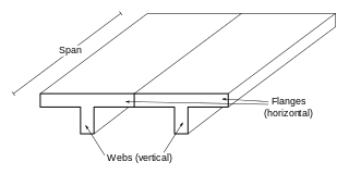
A T-beam, used in construction, is a load-bearing structure of reinforced concrete, wood or metal, with a T-shaped cross section. The top of the T-shaped cross section serves as a flange or compression member in resisting compressive stresses. The web of the beam below the compression flange serves to resist shear stress. When used for highway bridges the beam incorporates reinforcing bars in the bottom of the beam to resist the tensile stresses which occur during bending.

<span class="mw-page-title-main">Schierstein Bridge</span> Bridge in Hesse, Germany

The Schierstein Bridge is 1,282-meter (4,206 ft) long, four-lane highway bridge in Germany. It carries Bundesautobahn 643 over the Rhine River between Mainz-Mombach, Rhineland-Palatinate and Wiesbaden-Schierstein, Hesse. Crossing two arms of the Rhine and the intervening island of Rettbergsaue, the bridge is made of six individual structures, including 100 m (330 ft) from prestressed concrete. It was built between 1959 and 1962.

<span class="mw-page-title-main">Mirna Bridge</span> Bridge in Istria, Croatia

The Mirna Bridge is located between the Nova Vas and Višnjan interchanges of the A9 motorway in Istria, Croatia, spanning the Mirna River and the wide Mirna River valley. It is 1,378 metres (4,521 ft) long and comprises two traffic lanes. The bridge has been open for traffic since June 2005. The bridge is one of the most significant structures on the motorway. The bridge was designed by Zlatko Šavor.

<span class="mw-page-title-main">Old Rhine Bridge (Konstanz)</span> Bridge over the Rhine

The Old Rhine Bridge at Konstanz spans the Seerhein. It is a combined road and railway bridge. In addition to one track of the High Rhine Railway at kilometer 413.5, it carries the Konzilstraße, the road that connects the borough of Petershausen with the city centre. The road bridge carries two lanes into the city center and three lanes in the other direction. Additionally, there is a bicycle lane in both directions on the left and a sidewalk on the right. In the 19th century, distance markers were placed along the Rhine; they start counting kilometers at this bridge.

<span class="mw-page-title-main">Double tee</span> Type of load-bearing structure

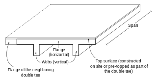
A double tee or double-T beam is a load-bearing structure that resembles two T-beams connected to each other side by side. The strong bond of the flange and the two webs creates a structure that is capable of withstanding high loads while having a long span. The typical sizes of double tees are up to 15 feet (4.6 m) for flange width, up to 5 feet (1.5 m) for web depth, and up to 80 feet (24 m) or more for span length. Double tees are pre-manufactured from prestressed concrete which allows construction time to be shortened.

<span class="mw-page-title-main">Rhine Bridge (Worms)</span> Bridge in Worms, Germany

The Worms Rhine Bridge is a two-track railway bridge that spans the Rhine river to the north of Worms, Germany, forming part of the Worms–Biblis railway.

<span class="mw-page-title-main">Burwell Bridge</span> United States historic place

The Burwell Bridge was a historic bridge on the northern edge of Burwell in Garfield County, Nebraska which was built in 1940–41. It was a steel girder bridge that brings Nebraska Highway 11 over the North Loup River. It is also known as the North Loup River Bridge and denoted as NEHBS Number GFOO-13. It was listed on the National Register of Historic Places in 1992, and was delisted in 2019.

<span class="mw-page-title-main">Gouritz River Bridge</span> Bridge in Mossel Bay

The Gouritz River Bridge on the N2 route between Cape Town and Port Elizabeth is a rigid-frame bridge which crosses the Gouritz River 34 kilometres (21 mi) west of Mossel Bay in the Western Cape.

References

  1. 1 2 3 "Rigid Frame Bridges" (PDF). www.marylandroads.com. Archived from the original (PDF) on 2017-08-03. Retrieved 2024-02-06.
  2. Encyclopædia Britannica, "Reinforced Concrete", November 2014
  3. 1 2 3 Portland Cement Association, "Analysis of Rigid Frame Concrete Bridges", Chicago, 1936.
  4. 1 2 "Reinforced Concrete Rigid Frame Bridges". www.ncdot.gov. North Carolina Department of Transportation. June 2013. Archived from the original on 2018-06-25. Retrieved 2024-02-06.
  5. 1 2 United States Department of the Interior, "National Register of Historic Places Continuation Sheet", p. 11
  6. "FINLEY Engineering Group: Finley: - Projects". Archived from the original on 2011-06-25. Retrieved 2014-11-05.
  7. Antónia Királyföld, Gábor Pál "CONCRETE STRUCTURES FRAME BRIDGES ON V-SHAPED SUPPORTS", Fib.bme.hu, 2012. [ dead link ]
  8. Middle East Economic Engineering Forum, "Rigid Frame Bridge", November 2014
  9. 1 2 3 4 Kabit, Shakya et al., Application of steel fibers in beam–column joints of rigid-framed railway bridges to reduce longitudinal and shear rebars, Construction and Building Materials, vol. 27, issue 1, pp. 482-489, Feb. 2012.
  10. 1 2 Shun Bo Zhao, Shi Ming Liu, Xiao Ke Li,"Design of Prestressed Concrete Continuous Rigid Frame Bridge with V-shaped Piers", Applied Mechanics and Materials, Vol.201-202, October 2012.