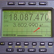
The decibel is a relative unit of measurement equal to one tenth of a bel (B). It expresses the ratio of two values of a power or root-power quantity on a logarithmic scale. Two signals whose levels differ by one decibel have a power ratio of 101/10 or root-power ratio of 101⁄20.

Software-defined radio (SDR) is a radio communication system where components that conventionally have been implemented in analog hardware are instead implemented by means of software on a personal computer or embedded system. While the concept of SDR is not new, the rapidly evolving capabilities of digital electronics render practical many processes which were once only theoretically possible.

The R-S-T system is used by amateur radio operators, shortwave listeners, and other radio hobbyists to exchange information about the quality of a radio signal being received. The code is a three digit number, with one digit each for conveying an assessment of the signal's readability, strength, and tone. The code was developed in 1934 by Amateur radio operator Arthur W. Braaten, W2BSR, and was similar to that codified in the ITU Radio Regulations, Cairo, 1938.
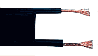
Twin-lead cable is a two-conductor flat cable used as a balanced transmission line to carry radio frequency (RF) signals. It is constructed of two stranded or solid copper or copper-clad steel wires, held a precise distance apart by a plastic ribbon. The uniform spacing of the wires is the key to the cable's function as a transmission line; any abrupt changes in spacing would reflect some of the signal back toward the source. The plastic also covers and insulates the wires. It is available with several different values of characteristic impedance, the most common type is 300 ohm.
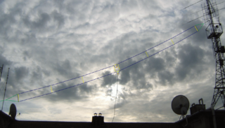
The Tilted Terminated Folded Dipole or Balanced Termination, Folded Dipole (BTFD) - also known as W3HH antenna - is a general-purpose shortwave antenna developed in the late 1940s by the United States Navy. It performs reasonably well over a broad frequency range, without marked dead spots in terms of either frequency, direction, or angle of radiation above the horizon.

A whip antenna is an antenna consisting of a straight flexible wire or rod. The bottom end of the whip is connected to the radio receiver or transmitter. A whip antenna is a form of monopole antenna. The antenna is designed to be flexible so that it does not break easily, and the name is derived from the whip-like motion that it exhibits when disturbed. Whip antennas for portable radios are often made of a series of interlocking telescoping metal tubes, so they can be retracted when not in use. Longer whips, made for mounting on vehicles and structures, are made of a flexible fiberglass rod around a wire core and can be up to 11 m long.

An antenna tuner is a passive electronic device inserted into the feedline between a radio transmitter and its antenna. Its purpose is to optimize power transfer by matching the impedance of the radio to the signal impedance at the end of the feedline connecting the antenna to the transmitter.
A loop antenna is a radio antenna consisting of a loop or coil of wire, tubing, or other electrical conductor, that for transmitting is usually fed by a balanced power source or for receiving feeds a balanced load. Within this physical description there are two distinct types:
A radio transmitter or receiver is connected to an antenna which emits or receives the radio waves. The antenna feed system or antenna feed is the cable or conductor, and other associated equipment, which connects the transmitter or receiver with the antenna and makes the two devices compatible. In a radio transmitter, the transmitter generates an alternating current of radio frequency, and the feed system feeds the current to the antenna, which converts the power in the current to radio waves. In a radio receiver, the incoming radio waves excite tiny alternating currents in the antenna, and the feed system delivers this current to the receiver, which processes the signal.

The AN/PRC-150(C) Falcon II Manpack Radio, is a tactical HF-SSB/ VHF-FM manpack radio manufactured by Harris Corporation. It holds an NSA certification for Type 1 encryption.
An amateur radio propagation beacon is a radio beacon, whose purpose is the investigation of the propagation of radio signals. Most radio propagation beacons use amateur radio frequencies. They can be found on LF, MF, HF, VHF, UHF, and microwave frequencies. Microwave beacons are also used as signal sources to test and calibrate antennas and receivers.

The Hallicrafters SX-117 was a radio communications receiver manufactured by the Hallicrafters company in the 1960s.

.

The Yaesu FT-817 is one of the smallest MF/HF/VHF/UHF multimode general-coverage amateur radio transceivers. The set is built by the Japanese Vertex Standard Corporation and is sold under the Yaesu brand. With internal battery pack, on board keyer, its all mode/all band capability and flexible antenna, the set is particularly well suited for portable use. The FT-817 is based on a similar circuit architecture as Yaesu's FT-857 and FT-897, so it is a compromise transceiver and incorporates its features to its low price.
In telecommunications, a field strength meter is an instrument that measures the electric field strength emanating from a transmitter.
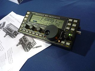
Elecraft, Inc. is an American manufacturer of amateur radio ("ham") equipment and kits, based in Watsonville, California. It was founded in 1998 by Wayne Burdick and Eric Swartz. The company's first product was the K2 transceiver; first prototyped in October 1997.
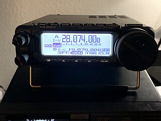
The Yaesu FT-891 is a HF and 6 meters all mode mobile amateur radio transceiver. The FT-891 was first announced to the public by Yaesu at the 2016 Dayton Hamvention. The radio has 100 watts output on CW, SSB, and FM modulations and 25 watts of output in AM. As a mobile transceiver the FT-891 is well suited for mobile installation in vehicles, and weighing less than 5 pounds it is often used for field activations such as Summits On The Air and Parks On The Air. The radio has been praised for its noise reduction and sensitive receiver. Common criticisms of the radio include its many menus that are difficult to navigate with its small screen, the lack of VHF/UHF capabilities, and lack of an internal antenna tuner. Although the radio lacks an internal sound card it still has input and output jacks for audio and be controlled over a USB cable allowing the radio to use digital modes such as WinLink, PSK31 and FT8.

The ICOM IC-705 is a multimode HF/VHF/UHF portable amateur radio transceiver. The radio has 5 watts of output when using its internal battery and 10 watts of output when using external power. With the rise in award programs such as Summits on the Air, and Parks on the Air this lightweight fully functional radio is a popular choice for people using them in the field. The IC-705 has support for a wide variety of commonly used amateur radio modes including ICOM's proprietary digital voice mode D-STAR. The IC-705 is also one of the first mainstream amateur radios to use SDR technology instead of the older superheterodyne design. Additionally the IC-705 has multiple extra features that are useful when operating in the field. Supporting the radio's D-STAR module is a GPS receiver to allow users to send their location though the D-STAR network as well as help locate nearby repeater systems. In addition to the GPS receiver the radio supports 2.4 GHz Wi-Fi which allows users to connect their computers or tablets to the IC-705 for running digital data modes such as PSK31, Winlink, and FT8. The radio has been praised for its size, easy to use menus, large easy to read screen and the quality of its build. Common criticisms of the radio include its lack of a built in antenna tuner and its price compared to other more powerful radios on the market.
The ICOM IC-7100 is a multimode HF/VHF/UHF mobile amateur radio transceiver. The IC-7100 has support for a wide variety of commonly used amateur radio modes including ICOMs proprietary digital voice mode DSTAR. Additionally the radio offers 100 watts on HF, 50 watts on VHF, and 35 watts on UHF. The IC-7100 is unique in that it has a large detachable control head with a slanted display so the transmitter can be installed elsewhere in a vehicle or home. The receiver used in the IC-7100 is a triple conversion superheterodyne and has excellent DSP and audio filters. The IC-7100 allows for connection to a computer over USB which enables the radio to be used for popular digital modes such as FT8, Winlink, and Packet Operation. Locations of nearby repeaters and sending APRS locations can be done with an optional GPS receiver attachment. Notable features that the IC-7100 lacks is an internal antenna tuner.

