Examples
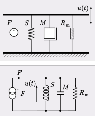
- Mechanical systems
- Force

- Electrical systems
- Voltage

All the fundamental variables of these systems have the same functional form.
In the systems sciences system equivalence is the behavior of a parameter or component of a system in a way similar to a parameter or component of a different system. Similarity means that mathematically the parameters and components will be indistinguishable from each other. Equivalence can be very useful in understanding how complex systems work.
Examples of equivalent systems are first- and second-order (in the independent variable) translational, electrical, torsional, fluidic, and caloric systems.
Equivalent systems can be used to change large and expensive mechanical, thermal, and fluid systems into a simple, cheaper electrical system. Then the electrical system can be analyzed to validate that the system dynamics will work as designed. This is a preliminary inexpensive way for engineers to test that their complex system performs the way they are expecting.
This testing is necessary when designing new complex systems that have many components. Businesses do not want to spend millions of dollars on a system that does not perform the way that they were expecting. Using the equivalent system technique, engineers can verify and prove to the business that the system will work. This lowers the risk factor that the business is taking on the project.
The following is a chart of equivalent variables for the different types of systems:
| System type | Flow variable | Effort variable | Compliance | Inductance | Resistance |
|---|---|---|---|---|---|
| Mechanical | dx/dt | F = force | spring (k) | mass (m) | damper (c) |
| Electrical | i = current | V = voltage | capacitance (C) | inductance (L) | resistance (R) |
| Thermal | qh = heat flow rate | ∆T = change in temperature | object (C) | inductance (L) [1] | conduction and convection (R) |
| Fluid | qm = mass flow rate, qv = volume flow rate | p = pressure, h = height | tank (C) | mass (m) | valve or orifice (R) |
The equivalents shown in the chart are not the only way to form mathematical analogies. In fact there are any number of ways to do this. A common requirement for analysis is that the analogy correctly models energy storage and flow across energy domains. To do this, the equivalences must be compatible. A pair of variables whose product is power (or energy) in one domain must be equivalent to a pair of variables in the other domain whose product is also power (or energy). These are called power conjugate variables. The thermal variables shown in the chart are not power conjugates and thus do not meet this criterion. See mechanical–electrical analogies for more detailed information on this. Even specifying power conjugate variables does not result in a unique analogy and there are at least three analogies of this sort in use. At least one more criterion is needed to uniquely specify the analogy, such as the requirement that impedance is equivalent in all domains as is done in the impedance analogy.
All the fundamental variables of these systems have the same functional form.
The system equivalence method may be used to describe systems of two types: "vibrational" systems (which are thus described - approximately - by harmonic oscillation) and "translational" systems (which deal with "flows"). These are not mutually exclusive; a system may have features of both. Similarities also exist; the two systems can often be analysed by the methods of Euler, Lagrange and Hamilton, so that in both cases the energy is quadratic in the relevant degree(s) of freedom, provided they are linear.
Vibrational systems are often described by some sort of wave (partial differential) equation, or oscillator (ordinary differential) equation. Furthermore, these sorts of systems follow the capacitor or spring analogy, in the sense that the dominant degree of freedom in the energy is the generalized position. In more physical language, these systems are predominantly characterised by their potential energy. This often works for solids, or (linearized) undulatory systems near equilibrium.
On the other hand, flow systems may be easier described by the hydraulic analogy or the diffusion equation. For example, Ohm's law was said to be inspired by Fourier's law (as well as the work of C.-L. Navier). [2] [3] [4] Other laws include Fick's laws of diffusion and generalized transport problems. The most important idea is the flux, or rate of transfer of some important physical quantity considered (like electric or magnetic fluxes). In these sorts of systems, the energy is dominated by the derivative of the generalized position (generalized velocity). In physics parlance, these systems tend to be kinetic energy-dominated. Field theories, in particular electromagnetism, draw heavily from the hydraulic analogy.

An electrical network is an interconnection of electrical components or a model of such an interconnection, consisting of electrical elements. An electrical circuit is a network consisting of a closed loop, giving a return path for the current. Thus all circuits are networks, but not all networks are circuits. Linear electrical networks, a special type consisting only of sources, linear lumped elements, and linear distributed elements, have the property that signals are linearly superimposable. They are thus more easily analyzed, using powerful frequency domain methods such as Laplace transforms, to determine DC response, AC response, and transient response.

In electrical engineering, impedance is the opposition to alternating current presented by the combined effect of resistance and reactance in a circuit.

Ohm's law states that the electric current through a conductor between two points is directly proportional to the voltage across the two points. Introducing the constant of proportionality, the resistance, one arrives at the three mathematical equations used to describe this relationship:
The electrical resistance of an object is a measure of its opposition to the flow of electric current. Its reciprocal quantity is electrical conductance, measuring the ease with which an electric current passes. Electrical resistance shares some conceptual parallels with mechanical friction. The SI unit of electrical resistance is the ohm, while electrical conductance is measured in siemens (S).
The lumped-element model is a simplified representation of a physical system or circuit that assumes all components are concentrated at a single point and their behavior can be described by idealized mathematical models. The lumped-element model simplifies the system or circuit behavior description into a topology. It is useful in electrical systems, mechanical multibody systems, heat transfer, acoustics, etc. This is in contrast to distributed parameter systems or models in which the behaviour is distributed spatially and cannot be considered as localized into discrete entities.
Acoustic impedance and specific acoustic impedance are measures of the opposition that a system presents to the acoustic flow resulting from an acoustic pressure applied to the system. The SI unit of acoustic impedance is the pascal-second per cubic metre, or in the MKS system the rayl per square metre (Rayl/m2), while that of specific acoustic impedance is the pascal-second per metre (Pa·s/m), or in the MKS system the rayl (Rayl). There is a close analogy with electrical impedance, which measures the opposition that a system presents to the electric current resulting from a voltage applied to the system.
Joule heating is the process by which the passage of an electric current through a conductor produces heat.
In electrical engineering and electronics, a network is a collection of interconnected components. Network analysis is the process of finding the voltages across, and the currents through, all network components. There are many techniques for calculating these values; however, for the most part, the techniques assume linear components. Except where stated, the methods described in this article are applicable only to linear network analysis.
Darcy's law is an equation that describes the flow of a fluid through a porous medium. The law was formulated by Henry Darcy based on results of experiments on the flow of water through beds of sand, forming the basis of hydrogeology, a branch of earth sciences. It is analogous to Ohm's law in electrostatics, linearly relating the volume flow rate of the fluid to the hydraulic head difference via the hydraulic conductivity. In fact, the Darcy's law is a special case of the Stokes equation for the momentum flux, in turn deriving from the momentum Navier-Stokes equation.

A magnetic circuit is made up of one or more closed loop paths containing a magnetic flux. The flux is usually generated by permanent magnets or electromagnets and confined to the path by magnetic cores consisting of ferromagnetic materials like iron, although there may be air gaps or other materials in the path. Magnetic circuits are employed to efficiently channel magnetic fields in many devices such as electric motors, generators, transformers, relays, lifting electromagnets, SQUIDs, galvanometers, and magnetic recording heads.
In physical systems, damping is the loss of energy of an oscillating system by dissipation. Damping is an influence within or upon an oscillatory system that has the effect of reducing or preventing its oscillation. Examples of damping include viscous damping in a fluid, surface friction, radiation, resistance in electronic oscillators, and absorption and scattering of light in optical oscillators. Damping not based on energy loss can be important in other oscillating systems such as those that occur in biological systems and bikes. Damping is not to be confused with friction, which is a type of dissipative force acting on a system. Friction can cause or be a factor of damping.
There are several formal analogies that can be made between electricity, which is invisible to the eye, and more familiar physical behaviors, such as the flowing of water or the motion of mechanical devices.

A bond graph is a graphical representation of a physical dynamic system. It allows the conversion of the system into a state-space representation. It is similar to a block diagram or signal-flow graph, with the major difference that the arcs in bond graphs represent bi-directional exchange of physical energy, while those in block diagrams and signal-flow graphs represent uni-directional flow of information. Bond graphs are multi-energy domain and domain neutral. This means a bond graph can incorporate multiple domains seamlessly.
Analogical models are a method of representing a phenomenon of the world, often called the "target system" by another, more understandable or analysable system. They are also called dynamical analogies.

The gyrator–capacitor model - sometimes also the capacitor-permeance model - is a lumped-element model for magnetic circuits, that can be used in place of the more common resistance–reluctance model. The model makes permeance elements analogous to electrical capacitance rather than electrical resistance. Windings are represented as gyrators, interfacing between the electrical circuit and the magnetic model.
In heat transfer, thermal engineering, and thermodynamics, thermal conductance and thermal resistance are fundamental concepts that describe the ability of materials or systems to conduct heat and the opposition they offer to the heat current. The ability to manipulate these properties allows engineers to control temperature gradient, prevent thermal shock, and maximize the efficiency of thermal systems. Furthermore, these principles find applications in a multitude of fields, including materials science, mechanical engineering, electronics, and energy management. Knowledge of these principles is crucial in various scientific, engineering, and everyday applications, from designing efficient temperature control, thermal insulation, and thermal management in industrial processes to optimizing the performance of electronic devices.
The impedance analogy is a method of representing a mechanical system by an analogous electrical system. The advantage of doing this is that there is a large body of theory and analysis techniques concerning complex electrical systems, especially in the field of filters. By converting to an electrical representation, these tools in the electrical domain can be directly applied to a mechanical system without modification. A further advantage occurs in electromechanical systems: Converting the mechanical part of such a system into the electrical domain allows the entire system to be analysed as a unified whole.
Mechanical–electrical analogies are the representation of mechanical systems as electrical networks. At first, such analogies were used in reverse to help explain electrical phenomena in familiar mechanical terms. James Clerk Maxwell introduced analogies of this sort in the 19th century. However, as electrical network analysis matured it was found that certain mechanical problems could more easily be solved through an electrical analogy. Theoretical developments in the electrical domain that were particularly useful were the representation of an electrical network as an abstract topological diagram using the lumped element model and the ability of network analysis to synthesise a network to meet a prescribed frequency function.
The mobility analogy, also called admittance analogy or Firestone analogy, is a method of representing a mechanical system by an analogous electrical system. The advantage of doing this is that there is a large body of theory and analysis techniques concerning complex electrical systems, especially in the field of filters. By converting to an electrical representation, these tools in the electrical domain can be directly applied to a mechanical system without modification. A further advantage occurs in electromechanical systems: Converting the mechanical part of such a system into the electrical domain allows the entire system to be analysed as a unified whole.
In control system theory, and various branches of engineering, a transfer function matrix, or just transfer matrix is a generalisation of the transfer functions of single-input single-output (SISO) systems to multiple-input and multiple-output (MIMO) systems. The matrix relates the outputs of the system to its inputs. It is a particularly useful construction for linear time-invariant (LTI) systems because it can be expressed in terms of the s-plane.