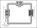
Analogy between a hydraulic circuit (left) and an electronic circuit (right).
Electronic-hydraulic analogies are the representation of electronic circuits by hydraulic circuits. Since electric current is invisible and the processes in play in electronics are often difficult to demonstrate, the various electronic components are represented by hydraulic equivalents. Electricity (as well as heat) was originally understood to be a kind of fluid, and the names of certain electric quantities (such as current) are derived from hydraulic equivalents.
The electronic–hydraulic analogy (derisively referred to as the drain-pipe theory by Oliver Lodge) [1] is the most widely used analogy for "electron fluid" in a metal conductor. As with all analogies, it demands an intuitive and competent understanding of the baseline paradigms (electronics and hydraulics), and in the case of the hydraulic analogy for electronics, students often have an inadequate knowledge of hydraulics.[2]
The analogy may also be reversed to explain or model hydraulic systems in terms of electronic circuits, as in expositions of the Windkessel effect.
Paradigms
There is no unique paradigm for establishing this analogy. Different paradigms have different strengths and weaknesses, depending on how and in what ways the intuitive understanding of the source of the analogy matches with phenomena in electronics.[2] Two paradigms can be used to introduce the concept to students using pressure induced by gravity or by pumps.
In the version with pressure induced by gravity, large tanks of water are held up high, or are filled to differing water levels, and the potential energy of the water head is the pressure source. This is reminiscent of electrical diagrams with an up arrow pointing to +V, grounded pins that otherwise are not shown connecting to anything, and so on. This has the advantage of associating electric potential with gravitational potential.
A second paradigm is a completely enclosed version with pumps providing pressure only and no gravity. This is reminiscent of a circuit diagram with a voltage source shown and the wires actually completing a circuit. This paradigm is further discussed below.
Other paradigms highlight the similarities between equations governing the flow of fluid and the flow of charge. Flow and pressure variables can be calculated in both steady and transient fluid flow situations with the use of the hydraulic ohm analogy.[3][4] Hydraulic ohms are the units of hydraulic impedance, which is defined as the ratio of pressure to volume flow rate. The pressure and volume flow variables are treated as phasors in this definition, so possess a phase as well as magnitude.[5]
A slightly different paradigm is used in acoustics, where acoustic impedance is defined as a relationship between acoustic pressure and acoustic particle velocity. In this paradigm, a large cavity with a hole is analogous to a capacitor that stores compressional energy when the time-dependent pressure deviates from atmospheric pressure. A hole (or long tube) is analogous to an inductor that stores kinetic energy associated with the flow of air.[6]
Hydraulic analogy with horizontal water flow
Voltage, current, and charge
In general, electric potential is equivalent to hydraulic head. This model assumes that the water is flowing horizontally, so that the force of gravity can be ignored. In this case, electric potential is equivalent to pressure. The voltage (or voltage drop or potential difference) is a difference in pressure between two points. Electric potential is usually measured in volts.
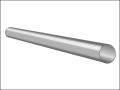
A relatively wide hose completely filled with water is equivalent to a conducting wire. A rigidly mounted pipe is equivalent to a trace on a circuit board. When comparing to a trace or wire, the hose or pipe should be thought of as having semi-permanent caps on the ends. Connecting one end of a wire to a circuit is equivalent to un-capping one end of the hose and attaching it to another. With few exceptions (such as a high-voltage power source), a wire with only one end attached to a circuit will do nothing; the hose remains capped on the free end, and thus adds nothing to the circuit.
A resistor is equivalent to a constriction in the bore of a pipe which requires more pressure to pass the same amount of water. All pipes have some resistance to flow, just as all wires and traces have some resistance to current.
A node (or junction) in Kirchhoff's junction rule is equivalent to a pipe tee. The net flow of water into a piping tee (filled with water) must equal the net flow out.
Capacitor:a flexible diaphragm sealed inside a pipe.
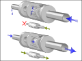
Inductor:a rotary vane pump with a heavy rotor, or a turbine placed in the current.
Voltage or current source:A dynamic pump with feedback control.
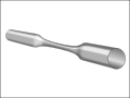
A capacitor is equivalent to a tank with one connection at each end and a rubber sheet dividing the tank in two lengthwise[7] (a hydraulic accumulator). When water is forced into one pipe, equal water is simultaneously forced out of the other pipe, yet no water can penetrate the rubber diaphragm. Energy is stored by the stretching of the rubber. As more current flows "through" the capacitor, the back-pressure (voltage) becomes greater, thus current "leads" voltage in a capacitor. As the back-pressure from the stretched rubber approaches the applied pressure, the current becomes less and less. Thus capacitors "filter out" constant pressure differences and slowly varying, low-frequency pressure differences, while allowing rapid changes in pressure to pass through.
An inductor is equivalent to a rotary vane pump with a heavy rotor placed in the current. The mass of the rotor and the surface area of the vanes restricts the water's ability to rapidly change its rate of flow (current) through the pump due to the effects of inertia, but, given time, a constant flowing stream will pass mostly unimpeded through the pump, as the rotor turns at the same speed as the water flow. The mass of the rotor and the surface area of its vanes are analogous to inductance, and friction between its axle and the axle bearings corresponds to the resistance that accompanies any non-superconducting inductor. An alternative inductor model is simply a long pipe, perhaps coiled into a spiral for convenience. This fluid-inertia device is used in real life as an essential component of a hydraulic ram. The inertia of the water flowing through the pipe produces the inductance effect; inductors "filter out" rapid changes in flow, while allowing slow variations in current to be passed through. The drag imposed by the walls of the pipe is somewhat analogous to parasitic resistance. In either model, the pressure difference (voltage) across the device must be present before the current will start moving, thus in inductors, voltage "leads" current. As the current increases, approaching the limits imposed by its own internal friction and of the current that the rest of the circuit can provide, the pressure drop across the device becomes lower and lower.
An ideal voltage source (ideal battery) or ideal current source is a dynamic pump with feedback control. A pressure meter on both sides shows that regardless of the current being produced, this kind of pump produces constant pressure difference. If one terminal is kept fixed at ground, another analogy is a large body of water at a high elevation, sufficiently large that the drawn water does not affect the water level. To create the analog of an ideal current source, use a positive displacement pump: A current meter (little paddle wheel) shows that when this kind of pump is driven at a constant speed, it maintains a constant speed of the little paddle wheel.
Other circuit elements
A simple one-way ball-type check valve, in its "open" state acts as a diode in its conducting state.
A pressure-actuated valve combined with a one-way check valve acts as a (field-effect) transistor.
Like a one-way check valve, a diode blocks current that flows the wrong way. Current that flows the right way goes through almost unchanged.
A simple A/C circuit consisting of an oscillating pump, a "diode" valve, and a "capacitor" tank. Any kind of motor could be used here to drive the pump, as long as it oscillates.
A diode is equivalent to a one-way check valve with a slightly leaky valve seat. As with a diode, a small pressure difference is needed before the valve opens. And like a diode, too much reverse bias can damage or destroy the valve assembly.
A transistor is a valve in which a diaphragm, controlled by a low-current signal (either constant current for a BJT or constant pressure for a FET), moves a plunger which affects the current through another section of pipe.
CMOS is a combination of two MOSFET transistors. As the input pressure changes, the pistons allow the output to connect to either zero or positive pressure.
A memristor is a needle valve operated by a flow meter. As water flows through in the forward direction, the needle valve restricts flow more; as water flows the other direction, the needle valve opens further, providing less resistance.
Practical application
On the basis of this analogy Johan van Veen developed around 1937[8] a method to compute tidal currents with an electric analogue. After the North Sea flood of 1953 in The Netherlands he elaborated this idea, which eventually lead to the analog computer ‘’Deltar’’, which was used to make the hydraulic computations for the closures in the framework of the Delta Works.
Principal equivalents
EM wave speed (velocity of propagation) is equivalent to the speed of sound in water. When a light switch is flipped, the electric wave travels very quickly through the wires.
Charge flow speed (drift velocity) is equivalent to the particle speed of water. The moving charges themselves move rather slowly.
DC is equivalent to a constant flow of water in a circuit of pipes.
Low frequencyAC is equivalent to water oscillating back and forth in a pipe.
Higher-frequency AC and transmission lines is somewhat equivalent to sound being transmitted through the water pipes, though this does not properly mirror the cyclical reversal of alternating electric current. As described, the fluid flow conveys pressure fluctuations, but fluids do not reverse at high rates in hydraulic systems, which the above "low frequency" entry does accurately describe. A better concept (if sound waves are to be the phenomenon) is that of direct current with high-frequency "ripple" superimposed.
If the differential equations are equivalent in form, the dynamics of the systems they describe will be related. The example hydraulic equations approximately describe the relationship between a constant, laminar flow in a cylindrical pipe and the difference in pressure at each end, as long as the flow is not analyzed near the ends of the pipe. The example electric equations approximately describe the relationship between a current in a straight wire and the difference in electric potential (voltage). In these two cases, the states of both systems are well-approximated by the differential equations above, and so the states are related. The assumptions that make these differential equations good approximates are needed for this relationship. Any deviations from the assumptions (e.g. pipe or wire is not straight, flow or current is changing over time, other factors are influencing potential) can make the relationship fail to hold. The differential equations for hydraulics and electronics above are special cases of the Navier–Stokes equations and Maxwell's equations, respectively, and the two are not equivalent in form.
If taken too far, the water analogy can create misconceptions. Negative transfer can occur when there is a mismatch between phenomena in the source (hydraulics) and the corresponding phenomena in the target (electronics).[2] For the analogy to be useful, one must remain aware of the regions where electricity and water behave very differently.
Fields (Maxwell equations, inductance): Electrons can push or pull other distant electrons via their fields, while water molecules experience forces only from direct contact with other molecules. For this reason, waves in water travel at the speed of sound, but waves in a sea of charge will travel much faster as the forces from one electron are applied to many distant electrons and not to only the neighbors in direct contact. In a hydraulic transmission line, the energy flows as mechanical waves through the water, but in an electric transmission line the energy flows as fields in the space surrounding the wires, and does not flow inside the metal. Also, an accelerating electron will drag its neighbors along while attracting them, both because of magnetic forces.
Charge: Unlike water, movable charge carriers can be positive or negative, and conductors can exhibit an overall positive or negative net charge. The mobile carriers in electric currents are usually electrons, but sometimes they are charged positively, such as the positive ions in an electrolyte, the H+ions in proton conductors or holes in p-type semiconductors and some (very rare) conductors.
Leaking pipes: The electric charge of an electrical circuit and its elements is usually almost equal to zero, hence it is (almost) constant. This is formalized in Kirchhoff's current law, which does not have an analogy to hydraulic systems, where the amount of the liquid is not usually constant. Even with incompressible liquid the system may contain such elements as pistons and open pools, so the volume of liquid contained in a part of the system can change. For this reason, continuing electric currents require closed loops rather than hydraulics' open source/sink resembling spigots and buckets.
Fluid velocity and resistance of metals: As with water hoses, the carrier drift velocity in conductors is directly proportional to current. However, water only experiences drag via the pipes' inner surface, while charges are slowed at all points within a metal, as with water forced through a filter. Also, typical velocity of charge carriers within a conductor is less than centimeters per minute, and the "electrical friction" is extremely high. If charges ever flowed as fast as water can flow in pipes, the electric current would be immense, and the conductors would become incandescently hot and perhaps vaporize. To model the resistance and the charge-velocity of metals, perhaps a pipe packed with sponge, or a narrow straw filled with syrup, would be a better analogy than a large-diameter water pipe.
Quantum mechanics: Solid conductors and insulators contain charges at more than one discrete level of atomic orbit energy, while the water in one region of a pipe can only have a single value of pressure. For this reason there is no hydraulic explanation for such things as a battery's charge pumping ability, a diode's depletion layer and voltage drop, solar cell functions, Peltier effect, etc., however equivalent devices can be designed which exhibit similar responses, although some of the mechanisms would only serve to regulate the flow curves rather than to contribute to the component's primary function.
In order for the model to be useful, the reader or student must have a substantial understanding of the model (hydraulic) system's principles. It also requires that the principles can be transferred to the target (electrical) system. Hydraulic systems are deceptively simple: the phenomenon of pump cavitation is a known, complex problem that few people outside of the fluid power or irrigation industries would understand. For those who do, the hydraulic analogy is amusing, as no "cavitation" equivalent exists in electrical engineering. The hydraulic analogy can give a mistaken sense of understanding that will be exposed once a detailed description of electrical circuit theory is required.
One must also consider the difficulties in trying to make an analogy match reality completely. The above "electrical friction" example, where the hydraulic analog is a pipe filled with sponge material, illustrates the problem: the model must be increased in complexity beyond any realistic scenario.
This page is based on this Wikipedia article Text is available under the CC BY-SA 4.0 license; additional terms may apply. Images, videos and audio are available under their respective licenses.