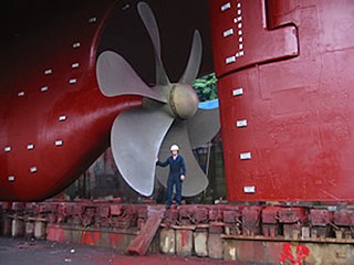
A propeller is a device with a rotating hub and radiating blades that are set at a pitch to form a helical spiral which, when rotated, exerts linear thrust upon a working fluid such as water or air. Propellers are used to pump fluid through a pipe or duct, or to create thrust to propel a boat through water or an aircraft through air. The blades are shaped so that their rotational motion through the fluid causes a pressure difference between the two surfaces of the blade by Bernoulli's principle which exerts force on the fluid. Most marine propellers are screw propellers with helical blades rotating on a propeller shaft with an approximately horizontal axis.
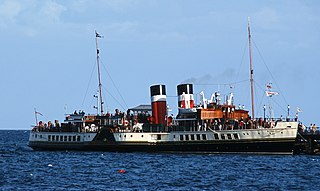
A steamship, often referred to as a steamer, is a type of steam-powered vessel, typically ocean-faring and seaworthy, that is propelled by one or more steam engines that typically move (turn) propellers or paddlewheels. The first steamships came into practical usage during the early 1800s; however, there were exceptions that came before. Steamships usually use the prefix designations of "PS" for paddle steamer or "SS" for screw steamer. As paddle steamers became less common, "SS" is assumed by many to stand for "steamship". Ships powered by internal combustion engines use a prefix such as "MV" for motor vessel, so it is not correct to use "SS" for most modern vessels.
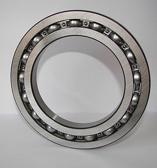
A ball bearing is a type of rolling-element bearing that uses balls to maintain the separation between the bearing races.
Fluid bearings are bearings in which the load is supported by a thin layer of rapidly moving pressurized liquid or gas between the bearing surfaces. Since there is no contact between the moving parts, there is no sliding friction, allowing fluid bearings to have lower friction, wear and vibration than many other types of bearings. Thus, it is possible for some fluid bearings to have near-zero wear if operated correctly.
A bearing is a machine element that constrains relative motion to only the desired motion and reduces friction between moving parts. The design of the bearing may, for example, provide for free linear movement of the moving part or for free rotation around a fixed axis; or, it may prevent a motion by controlling the vectors of normal forces that bear on the moving parts. Most bearings facilitate the desired motion by minimizing friction. Bearings are classified broadly according to the type of operation, the motions allowed, or the directions of the loads (forces) applied to the parts.

A connecting rod, also called a 'con rod', is the part of a piston engine which connects the piston to the crankshaft. Together with the crank, the connecting rod converts the reciprocating motion of the piston into the rotation of the crankshaft. The connecting rod is required to transmit the compressive and tensile forces from the piston. In its most common form, in an internal combustion engine, it allows pivoting on the piston end and rotation on the shaft end.

A plain bearing, or more commonly sliding contact bearing and slide bearing, is the simplest type of bearing, comprising just a bearing surface and no rolling elements. Therefore, the journal slides over the bearing surface. The simplest example of a plain bearing is a shaft rotating in a hole. A simple linear bearing can be a pair of flat surfaces designed to allow motion; e.g., a drawer and the slides it rests on or the ways on the bed of a lathe.

In mechanical engineering, a rolling-element bearing, also known as a rolling bearing, is a bearing which carries a load by placing rolling elements between two concentric, grooved rings called races. The relative motion of the races causes the rolling elements to roll with very little rolling resistance and with little sliding.

A thrust bearing is a particular type of rotary bearing. Like other bearings they permanently rotate between parts, but they are designed to support a predominantly axial load.

Babbitt metal or bearing metal is any of several alloys used for the bearing surface in a plain bearing.

A pillow block bearing is a pedestal used to support a rotating shaft with the help of compatible bearings and various accessories. The assembly consists of a mounting block which houses a bearing. The block is mounted to a foundation, and a shaft is inserted, allowing the inner part of the bearing/shaft to rotate. The inside of the bearing is typically 0.025 millimetres (0.001 in) larger diameter than the shaft to ensure a tight fit. Set screws, locking collars, or set collars are commonly used to secure the shaft. Housing material for a pillow block is typically made of cast iron or cast steel.
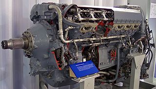
The Rolls-Royce Griffon is a British 37-litre capacity, 60-degree V-12, liquid-cooled aero engine designed and built by Rolls-Royce Limited. In keeping with company convention, the Griffon was named after a bird of prey, in this case the griffon vulture.
Anthony George Maldon Michell FRS was an Australian mechanical engineer of the early 20th century.

Tapered roller bearings are rolling element bearings that can support axial forces as well as radial forces.

A reduction drive is a mechanical device to shift rotational speed. A planetary reduction drive is a small scale version using ball bearings in an epicyclic arrangement instead of toothed gears.

Marine propulsion is the mechanism or system used to generate thrust to move a watercraft through water. While paddles and sails are still used on some smaller boats, most modern ships are propelled by mechanical systems consisting of an electric motor or internal combustion engine driving a propeller, or less frequently, in pump-jets, an impeller. Marine engineering is the discipline concerned with the engineering design process of marine propulsion systems.
A stave bearing is a simple journal bearing where a shaft rotates in a bearing housing. Rather than the usual arrangement where the fixed part of the bearing surrounds most of the circumference of the shaft in one or two pieces, a stave bearing uses a large number of axial staves to support the shaft. A large housing is made with grooves running along the shaft, these grooves being filled with strips of suitable material, originally wood.

Albert Kingsbury was an American engineer, inventor and entrepreneur. He was responsible for over fifty patents obtained between the years 1902 to 1930. Kingsbury is most famous for his hydrodynamic thrust bearing which uses a thin film of oil to support weights of up to 220 tons. This bearing extended the service life of many types of machinery during the early 20th century. It was primarily outfitted on Navy ships during World War I and World War II.

The yaw bearing is the most crucial and cost intensive component of a yaw system found on modern horizontal axis wind turbines. The yaw bearing must cope with enormous static and dynamic loads and moments during the wind turbine operation, and provide smooth rotation characteristics for the orientation of the nacelle under all weather conditions. It has also to be corrosion and wear resistant and extremely long lasting. It should last for the service life of the wind turbine) while being cost effective.
The Michel engine was an unusual form of opposed-piston engine. It was unique in that its cylinders, instead of being open-ended cylinders containing two pistons, were instead joined in a Y-shape and had three pistons working within them.

