Thyristor-switched capacitor

Last updated

A thyristor-switched capacitor (TSC) is a type of equipment used for compensating reactive power in electrical power systems. It consists of a power capacitor connected in series with a bidirectional thyristor valve and, usually, a current limiting reactor (inductor). The thyristor switched capacitor is an important component of a Static VAR Compensator (SVC), [1] [2] where it is often used in conjunction with a thyristor controlled reactor (TCR). Static VAR compensators are a member of the Flexible AC transmission system (FACTS) family.

Contents

Circuit diagram

A TSC is usually a three-phase assembly, connected either in a delta or a star arrangement. Unlike the TCR, a TSC generates no harmonics and so requires no filtering. For this reason, some SVCs have been built with only TSCs . [3] This can lead to a relatively cost-effective solution where the SVC only requires capacitive reactive power, although a disadvantage is that the reactive power output can only be varied in steps. Continuously variable reactive power output is only possible where the SVC contains a TCR or another variable element such as a STATCOM.

Thyristor Switched Capacitor circuit.png

Operating principles

Unlike the TCR, the TSC is only ever operated fully on or fully off. An attempt to operate a TSC in ‘’phase control’’ would result in the generation of very large amplitude resonant currents, leading to overheating of the capacitor bank and thyristor valve, and harmonic distortion in the AC system to which the SVC is connected.

Steady state current

When the TSC is on, or ‘’deblocked’’, the current leads the voltage 90° (as with any capacitor). The rms current is given by:

Where:

Vsvc is the rms value of the line-to-line busbar voltage to which the SVC is connected

Ctsc is the total TSC capacitance per phase

Ltsc is the total TSC inductance per phase

f is the frequency of the AC system

The TSC forms an inductor-capacitor (LC) resonant circuit with a characteristic frequency of :

The tuned frequency is usually chosen to be in the range 150-250 Hz on 60 Hz systems or 120-210 Hz on 50 Hz systems. [4] It is an economic choice between the size of the TSC reactor (which increases with decreasing frequency) and the need to protect the thyristor valve from excessive oscillatory currents when the TSC is turned on at an incorrect point of wave (‘’misfiring’’).

The TSC is usually tuned to a non-integer harmonic of the mains frequency so as to avoid the risk of the TSC being overloaded by harmonic currents flowing into it from the AC system.

Off-state voltage

When the TSC is switched off, or ‘’blocked’’, no current flows and the voltage is supported by the thyristor valve. After the TSC has been switched off for a long time (hours) the capacitor will be fully discharged, and the thyristor valve will experience only the AC voltage of the SVC busbar. However, when the TSC turns off, it does so at zero current, corresponding to peak capacitor voltage. The capacitor only discharges very slowly, so the voltage experienced by the thyristor valve will reach a peak of more than twice the peak AC voltage, about half a cycle after blocking. The thyristor valve needs to contain enough thyristors in series to withstand this voltage safely.

Thyristor switched capacitor waveforms 1.png

Deblocking – normal conditions

When the TSC is turned on ("deblocked") again, care must be taken to choose the correct instant in order to avoid creating very large oscillatory currents. Since the TSC is a resonant circuit, any sudden shock excitation will produce a high-frequency ringing effect which could damage the thyristor valve.

The optimum time to turn on a TSC is when the capacitor is still charged to its normal peak value and the turn-on command is sent at the minimum of valve voltage. If the TSC is deblocked at this point, the transition back into the conducting state will be smooth.

Thyristor switched capacitor waveforms 2.png

Deblocking – abnormal conditions

Sometimes, however, the TSC may turn on at an incorrect instant (as a result of a control or measurement fault), or the capacitor may become charged to a voltage above the normal value so that even at the minimum of valve voltage, a large transient current results. The current in the TSC will then consist of a fundamental-frequency component (50 Hz or 60 Hz) superimposed on a much larger current at the tuned frequency of the TSC. This transient current can take hundreds of milliseconds to die away, during which time the cumulative heating in the thyristors may be excessive.

Thyristor switched capacitor waveforms 3.png

Main equipment

A TSC normally comprises three main items of equipment: the main capacitor bank, the thyristor valve and a current-limiting reactor, which is usually air-cored.

Capacitor bank

The largest item of equipment in a TSC, the capacitor bank, is constructed from rack-mounted outdoor capacitor units, each unit typically having a rating in the range 500 – 1000 kilovars (kVAr).

TSC reactor

The function of the TSC reactor is to limit the peak current and rate of rise of current (di/dt) when the TSC turns on at an incorrect time. The reactor is usually an air-cored reactor, similar to that of a TCR, but smaller. The size and cost of the TSC reactor is heavily influenced by the tuning frequency of the TSC, lower frequencies requiring larger reactors.

The TSC reactor is usually located outside, close to the main capacitor bank.

Thyristor valve

The thyristor valve typically consists of 10-30 inverse-parallel-connected pairs of thyristors connected in series. The inverse-parallel connection is needed because most commercially available thyristors can conduct current in only one direction. The series connection is needed because the maximum voltage rating of commercially available thyristors (up to approximately 8.5 kV) is insufficient for the voltage at which the TCR is connected. For some low-voltage applications, it may be possible to avoid the series-connection of thyristors; in such cases the thyristor valve is simply an inverse-parallel connection of two thyristors.

Typical TSC valve Thyristor switched capacitor valve.png
Typical TSC valve

In addition to the thyristors themselves, each inverse-parallel pair of thyristors has a resistor–capacitor ‘’snubber’ circuit connected across it, to force the voltage across the valve to divide uniformly amongst the thyristors and to damp the "commutation overshoot" which occurs when the valve turns off.

The thyristor valve for a TSC is very similar to that of a TCR, but (for a given AC voltage) generally has between 1.5 and 2 times as many thyristors connected in series because of the need to withstand both the AC voltage and the trapped capacitor voltage after blocking.

The thyristor valve is usually installed in a purpose-built, ventilated building, or a modified shipping container. Cooling for the thyristors and snubber resistors is usually provided by deionised water.

Special types of TSC

Some TSCs have been built with the capacitor and inductor arranged not as a simple tuned LC circuit but rather as a damped filter. This type of arrangement is useful when the power system to which the TSC is connected contains significant levels of background harmonic distortion, or where there is a risk of resonance between the power system and the TSC.

In several “Relocatable SVCs” built for National Grid (Great Britain), [3] three TSCs of unequal size were provided, in each case with the capacitor and inductor arranged as a “C-type” damped filter. In a C-type filter, the capacitor is split into two series-connected sections. A damping resistor is connected across one of the two capacitor sections and the inductor, the tuned frequency of this section being equal to the grid frequency. In this way, damping is provided for harmonic frequencies but the circuit incurs no power loss at grid frequency.

See also

Related Research Articles

In electrical engineering, the power factor of an AC power system is defined as the ratio of the real power absorbed by the load to the apparent power flowing in the circuit. Real power is the average of the instantaneous product of voltage and current and represents the capacity of the electricity for performing work. Apparent power is the product of RMS current and voltage. Due to energy stored in the load and returned to the source, or due to a non-linear load that distorts the wave shape of the current drawn from the source, the apparent power may be greater than the real power, so more current flows in the circuit than would be required to transfer real power alone. A power factor magnitude of less than one indicates the voltage and current are not in phase, reducing the average product of the two. A negative power factor occurs when the device generates real power, which then flows back towards the source.

<span class="mw-page-title-main">High-voltage direct current</span> Electric power transmission system

A high-voltage direct current (HVDC) electric power transmission system uses direct current (DC) for electric power transmission, in contrast with the more common alternating current (AC) transmission systems.

<span class="mw-page-title-main">Rectifier</span> Electrical device that converts AC to DC

A rectifier is an electrical device that converts alternating current (AC), which periodically reverses direction, to direct current (DC), which flows in only one direction. The reverse operation is performed by an inverter.

<span class="mw-page-title-main">Power inverter</span> Device that changes direct current (DC) to alternating current (AC)

A power inverter, inverter or invertor is a power electronic device or circuitry that changes direct current (DC) to alternating current (AC). The resulting AC frequency obtained depends on the particular device employed. Inverters do the opposite of rectifiers which were originally large electromechanical devices converting AC to DC.

A flexible alternating current transmission system (FACTS) is a system composed of static equipment used for the alternating current (AC) transmission of electrical energy. It is meant to enhance controllability and increase power transfer capability of the network. It is generally a power electronics-based system.

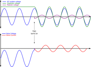
A static VAR compensator (SVC) is a set of electrical devices for providing fast-acting reactive power on high-voltage electricity transmission networks. SVCs are part of the flexible AC transmission system device family, regulating voltage, power factor, harmonics and stabilizing the system. A static VAR compensator has no significant moving parts. Prior to the invention of the SVC, power factor compensation was the preserve of large rotating machines such as synchronous condensers or switched capacitor banks.

<span class="mw-page-title-main">HVDC converter station</span>

An HVDC converter station is a specialised type of substation which forms the terminal equipment for a high-voltage direct current (HVDC) transmission line. It converts direct current to alternating current or the reverse. In addition to the converter, the station usually contains:

<span class="mw-page-title-main">AC power</span> Power in alternating current systems

In an electric circuit, instantaneous power is the time rate of flow of energy past a given point of the circuit. In alternating current circuits, energy storage elements such as inductors and capacitors may result in periodic reversals of the direction of energy flow. Its SI unit is the watt.

<span class="mw-page-title-main">Variable-frequency drive</span> Type of adjustable-speed drive

A variable-frequency drive, variable-speed drives, AC drives, micro drives, inverter drives, or drives) is a type of AC motor drive that controls speed and torque by varying the frequency of the input electricity. Depending on its topology, it controls the associated voltage or current variation.

An induction generator or asynchronous generator is a type of alternating current (AC) electrical generator that uses the principles of induction motors to produce electric power. Induction generators operate by mechanically turning their rotors faster than synchronous speed. A regular AC induction motor usually can be used as a generator, without any internal modifications. Because they can recover energy with relatively simple controls, induction generators are useful in applications such as mini hydro power plants, wind turbines, or in reducing high-pressure gas streams to lower pressure.

A static synchronous compensator (STATCOM), originally known as a static synchronous condenser (STATCON), is a regulating device shunt-connected to alternating current electricity transmission network. It is based on a power electronics voltage-source converter and can act as either a source or sink of reactive AC power to an electricity network. If connected to a source of power it can also provide active AC power. It is a member of the FACTS family of devices, that became possible in 1990s due to availability of powerful gate turn-off thyristors (GTO). STATCOM is inherently modular and electable.

<span class="mw-page-title-main">Electric power system</span> Network of electrical component deployed to generate, transmit & distribute electricity

An electric power system is a network of electrical components deployed to supply, transfer, and use electric power. An example of a power system is the electrical grid that provides power to homes and industries within an extended area. The electrical grid can be broadly divided into the generators that supply the power, the transmission system that carries the power from the generating centers to the load centers, and the distribution system that feeds the power to nearby homes and industries.

<span class="mw-page-title-main">GK Dürnrohr</span>

The GK Dürnrohr was a high-voltage direct current back-to-back scheme west of Dürnrohr substation, which was used for the energy exchange between Austria and Czechoslovakia between 1983 and 1996. The installation is no longer in use.

<span class="mw-page-title-main">Sakuma Dam</span> Dam on the Tenryū River in Japan

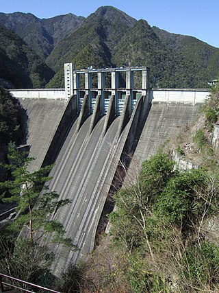
The Sakuma Dam is a dam on the Tenryū River, located on the border of Toyone, Kitashitara District, Aichi Prefecture on the island of Honshū, Japan. It is one of the tallest dams in Japan and supports a 350 MW hydroelectric power station. Nearby a frequency converter station is installed, allowing interchange of power between Japan's 50 Hz and 60 Hz AC networks.

The Levis De-Icer is a High voltage direct current (HVDC) system, aimed at de-icing multiple AC power lines in Quebec, Canada. It is the only HVDC system not used for power transmission.

In an electric power transmission system, a thyristor-controlled reactor (TCR) is a reactance connected in series with a bidirectional thyristor valve. The thyristor valve is phase-controlled, which allows the value of delivered reactive power to be adjusted to meet varying system conditions. Thyristor-controlled reactors can be used for limiting voltage rises on lightly loaded transmission lines. Another device which used to be used for this purpose is a magnetically controlled reactor (MCR), a type of magnetic amplifier otherwise known as a transductor.

The Chandrapur back-to-back HVDC station is a back-to-back HVDC connection between the western and southern regions in India, located close to the city of Chandrapur. Its main purpose is to export power from the Chandrapur Super Thermal Power Station to the southern region of the Indian national power grid. It is owned by Power Grid Corporation of India.

An HVDC converter converts electric power from high voltage alternating current (AC) to high-voltage direct current (HVDC), or vice versa. HVDC is used as an alternative to AC for transmitting electrical energy over long distances or between AC power systems of different frequencies. HVDC converters capable of converting up to two gigawatts (GW) and with voltage ratings of up to 900 kilovolts (kV) have been built, and even higher ratings are technically feasible. A complete converter station may contain several such converters in series and/or parallel to achieve total system DC voltage ratings of up to 1,100 kV.

<span class="mw-page-title-main">Line trap</span>

A line trap, also known as wave trap, or high-frequency stopper, is a maintenance-free parallel resonant circuit, mounted inline on high-voltage (HV) AC transmission power lines to prevent the transmission of high frequency carrier signals of power line communication to unwanted destinations. Line traps are cylinder-like structures connected in series with HV transmission lines. A line trap is also called a wave trap.

This glossary of power electronics is a list of definitions of terms and concepts related to power electronics in general and power electronic capacitors in particular. For more definitions in electric engineering, see Glossary of electrical and electronics engineering. For terms related to engineering in general, see Glossary of engineering.

References

  1. Song, Y.H., Johns, A.T. Flexible ac transmission systems. IEE. ISBN   0-85296-771-3
  2. Hingorani, N.G. & Gyugyi, L. Understanding FACTS - Concepts and Technology of Flexible AC Transmission Systems. IEEE. ISBN   0-7803-3455-8.
  3. 1 2 [Horwill, C., Young, D.J., Wong, K.T.G. A design for a relocatable tertiary connected SVC. IEE Conference on AC and DC power transmission, London, 1994.
  4. R. Mohan Mathur; Rajiv K. Varma (27 February 2002). Thyristor-Based FACTS Controllers for Electrical Transmission Systems. John Wiley & Sons. pp. 73–75. ISBN   978-0-471-20643-9.