
Electric power transmission is the bulk movement of electrical energy from a generating site, such as a power plant, to an electrical substation. The interconnected lines which facilitate this movement are known as a transmission network. This is distinct from the local wiring between high-voltage substations and customers, which is typically referred to as electric power distribution. The combined transmission and distribution network is part of electricity delivery, known as the electrical grid.
In telecommunications and professional audio, a balanced line or balanced signal pair is a circuit consisting of two conductors of the same type, each of which have equal impedances along their lengths and equal impedances to ground and to other circuits. The chief advantage of the balanced line format is good rejection of common-mode noise and interference when fed to a differential device such as a transformer or differential amplifier. Common forms of balanced line are twin-lead, used for radio frequency signals and twisted pair, used for lower frequencies. They are to be contrasted to unbalanced lines, such as coaxial cable, which is designed to have its return conductor connected to ground, or circuits whose return conductor actually is ground. Balanced and unbalanced circuits can be interfaced using a device called a balun.
In telecommunication and electrical engineering, a phantom circuit is an electrical circuit derived from suitably arranged wires with one or more conductive paths being a circuit in itself and at the same time acting as one conductor of another circuit.

In electrical engineering, a transmission line is a specialized cable or other structure designed to conduct electromagnetic waves in a contained manner. The term applies when the conductors are long enough that the wave nature of the transmission must be taken into account. This applies especially to radio-frequency engineering because the short wavelengths mean that wave phenomena arise over very short distances. However, the theory of transmission lines was historically developed to explain phenomena on very long telegraph lines, especially submarine telegraph cables.
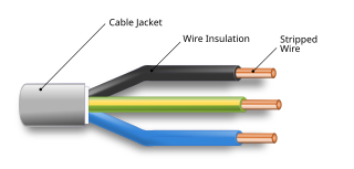
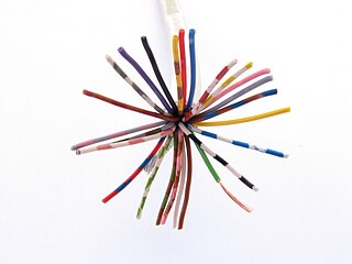
An electrical cable is an assembly of one or more wires running side by side or bundled, which is used to carry electric current.

Twisted pair cabling is a type of wiring in which two conductors of a single circuit are twisted together for the purposes of improving electromagnetic compatibility. Compared to a single conductor or an untwisted balanced pair, a twisted pair reduces electromagnetic radiation from the pair and crosstalk between neighboring pairs and improves rejection of external electromagnetic interference. It was invented by Alexander Graham Bell.
An overhead line or overhead wire is an electrical cable that is used to transmit electrical energy to electric locomotives, trolleybuses or trams. It is known variously as:

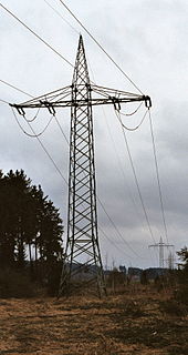
A transmission tower, also known as an electricity pylon or simply a pylon in British English and as a hydro tower in Canadian English, is a tall structure, usually a steel lattice tower, used to support an overhead power line.

A dead-end tower is a fully self-supporting structure used in construction of overhead power lines. A dead-end transmission tower uses horizontal strain insulators at the end of conductors. Dead-end towers may be used at a substation as a transition to a "slack span" entering the equipment, when the circuit changes to a buried cable, when a transmission line changes direction by more than a few degrees, or at intervals along a straight run to limit the extent of a catastrophic collapse.

A utility pole is a column or post typically made out of wood used to support overhead power lines and various other public utilities, such as electrical cable, fiber optic cable, and related equipment such as transformers and street lights. It can be referred to as a transmission pole, telephone pole, telecommunication pole, power pole, hydro pole, telegraph pole, or telegraph post, depending on its application. A Stobie pole is a multi-purpose pole made of two steel joists held apart by a slab of concrete in the middle, generally found in South Australia.
A single-wire transmission line is a method of transmitting electrical power or signals using only a single electrical conductor. This is in contrast to the usual use of a pair of wires providing a complete circuit, or an electrical cable likewise containing two conductors for that purpose.

An overhead power line is a structure used in electric power transmission and distribution to transmit electrical energy across large distances. It consists of one or more uninsulated electrical cables suspended by towers or poles.

Differential signalling is a method for electrically transmitting information using two complementary signals. The technique sends the same electrical signal as a differential pair of signals, each in its own conductor. The pair of conductors can be wires in a twisted-pair or ribbon cable or traces on a printed circuit board.
A traction network or traction power network is an electricity grid for the supply of electrified rail networks. The installation of a separate traction network generally is done only if the railway in question uses alternating current (AC) with a frequency lower than that of the national grid, such as in Germany, Austria and Switzerland.
In telecommunications and electrical engineering in general, an unbalanced line is a pair of conductors intended to carry electrical signals, which have unequal impedances along their lengths and to ground and other circuits. Examples of unbalanced lines are coaxial cable or the historic earth return system invented for the telegraph, but rarely used today. Unbalanced lines are to be contrasted with balanced lines, such as twin-lead or twisted pair which use two identical conductors to maintain impedance balance throughout the line. Balanced and unbalanced lines can be interfaced using a device called a balun.
In an electric power system, a fault or fault current is any abnormal electric current. For example, a short circuit is a fault in which a live wire touches a neutral or ground wire. An open-circuit fault occurs if a circuit is interrupted by a failure of a current-carrying wire or a blown fuse or circuit breaker. In three-phase systems, a fault may involve one or more phases and ground, or may occur only between phases. In a "ground fault" or "earth fault", current flows into the earth. The prospective short-circuit current of a predictable fault can be calculated for most situations. In power systems, protective devices can detect fault conditions and operate circuit breakers and other devices to limit the loss of service due to a failure.
An optical ground wire is a type of cable that is used in overhead power lines. Such cable combines the functions of grounding and communications. An OPGW cable contains a tubular structure with one or more optical fibers in it, surrounded by layers of steel and aluminum wire. The OPGW cable is run between the tops of high-voltage electricity pylons. The conductive part of the cable serves to bond adjacent towers to earth ground, and shields the high-voltage conductors from lightning strikes. The optical fibers within the cable can be used for high-speed transmission of data, either for the electrical utility's own purposes of protection and control of the transmission line, for the utility's own voice and data communication, or may be leased or sold to third parties to serve as a high-speed fiber interconnection between cities.
In civil engineering, undergrounding is the replacement of overhead cables providing electrical power or telecommunications, with underground cables. It demonstrates the higher technology in developed countries for fire prevention and to make the power lines less susceptible to outages during high wind thunderstorms or heavy snow or ice storms. An added benefit of undergrounding is the aesthetic quality of the landscape without the powerlines. Undergrounding can increase the initial costs of electric power transmission and distribution but may decrease operational costs over the lifetime of the cables.

Star-quad cable is a four-conductor cable that has a special quadrupole geometry which provides magnetic immunity when used in a balanced line. Four conductors are used to carry the two legs of the balanced line. All four conductors must be an equal distance from a common point. The four conductors are arranged in a four-pointed star. Opposite points of the star are connected together at each end of the cable to form each leg of the balanced circuit.
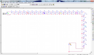
Performance modelling is the abstraction of a real system into a simplified representation to enable the prediction of performance. The creation of a model can provide insight into how a proposed or actual system will or does work. This can, however, point towards different things to people belonging to different fields of work.


