Electronic timer used to detect and recover from computer malfunctions
A watchdog timer integrated circuit (Texas Instruments TPS3823). One pin receives the timer restart ("kick" ) signal from the computer; another pin outputs the timeout signal.
A watchdog timer (WDT, or simply a watchdog), sometimes called a computer operating properly timer (COP timer), is an electronic or software timer that is used to detect and recover from computer malfunctions.[1] Watchdog timers are widely used in computers to facilitate automatic correction of temporary hardware faults, and to prevent errant or malevolent software from disrupting system operation.
During normal operation, the computer regularly restarts the watchdog timer to prevent it from elapsing, or timing out. If, due to a hardware fault or program error, the computer fails to restart the watchdog, the timer will elapse and generate a timeout signal. The timeout signal is used to initiate corrective actions. The corrective actions typically include placing the computer and associated hardware in a safe state and invoking a computer reboot.
Microcontrollers often include an integrated, on-chip watchdog. In other computers the watchdog may reside in a nearby chip that connects directly to the CPU, or it may be located on an external expansion card in the computer's chassis.
Applications
Watchdog timers are essential in remote, automated systems such as this Mars Exploration Rover.
Watchdog timers are commonly found in embedded systems and other computer-controlled equipment where humans cannot easily access the equipment or would be unable to react to faults in a timely manner. In such systems, the computer cannot depend on a human to invoke a reboot if it hangs; it must be self-reliant. For example, remote embedded systems such as space probes are not physically accessible to human operators; these could become permanently disabled if they were unable to autonomously recover from faults. In robots and other automated machines, a fault in the control computer could cause equipment damage or injuries before a human could react, even if the computer is easily accessed. A watchdog timer is usually employed in cases like these.
Watchdog timers are also used to monitor and limit software execution time on a normally functioning computer. For example, a watchdog timer may be used when running untrusted code in a sandbox, to limit the CPU time available to the code and thus prevent some types of denial-of-service attacks.[2] In real-time operating systems, a watchdog timer may be used to monitor a time-critical task to ensure it completes within its maximum allotted time and, if it fails to do so, to terminate the task safely and report the failure.
Architecture and operation
Restarting
The act of restarting a watchdog timer is commonly referred to as kicking[a] the watchdog.[3][4] In electronic watchdogs, kicking is typically done by writing to a watchdog control port or by setting a particular bit in a register. Alternatively, some tightly coupled[b] watchdog timers are kicked by executing a special machine language instruction. An example of this is the CLRWDT (clear watchdog timer) instruction found in the instruction set of some PIC microcontrollers.
In computers that are running operating systems, electronic watchdog restarts are usually invoked through a device driver. For example, in the Linux operating system, a user space program will kick the watchdog by interacting with the watchdog device driver, typically by writing a zero character to /dev/watchdog or by calling a KEEPALIVE ioctl.[5] The device driver, which serves to abstract the watchdog hardware from user space programs, may also be used to configure the time-out period and start and stop the timer.
Some watchdog timers only allow kicks during a time window. Kicks occurring outside the window have no effect on the timer and may be treated as faults.
Some watchdog timers will only allow kicks during a specific time window. The window timing is usually relative to the previous kick or, if the watchdog has not yet been kicked, to the moment the watchdog was enabled. The window begins after a delay following the previous kick, and ends after a further delay. If the computer attempts to kick the watchdog before or after the window, the watchdog will not be restarted, and in some implementations this will be treated as a fault and trigger corrective action.[6]
Enabling
A watchdog timer is said to be enabled when operating and disabled when idle. Upon power-up, a watchdog may be unconditionally enabled or it may be initially disabled and require an external signal to enable it. In the latter case, the enabling signal may be automatically generated by hardware or it may be generated under software control.
Unconditionally enabled watchdog
Watchdog with enable input signal
When automatically generated, the enabling signal is typically derived from the computer reset signal. In some systems the reset signal is directly used to enable the watchdog. In others, the reset signal is delayed so that the watchdog will become enabled at some later time following the reset. This delay allows time for the computer to boot before the watchdog is enabled. Without this delay, the watchdog would timeout and invoke a subsequent reset before the computer can run its application software — the software which kicks the watchdog — and the system would become stuck in an endless cycle of incomplete reboots.
Single-stage watchdog
Watchdog timers come in many configurations, and many allow their configurations to be altered. For example, the watchdog and CPU may share a common clock signal as shown in the block diagram below, or they may have independent clock signals or in some cases the watchdog may have no clock signal at all. A basic watchdog timer has a single timer which, upon timeout, typically will reset the CPU:
Multistage watchdog
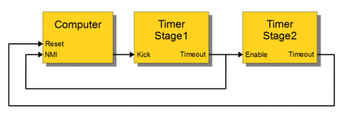
Two or more timers are sometimes cascaded to form a multistage watchdog timer, where each timer is referred to as a timer stage, or simply a stage. For example, the block diagram below shows a three-stage watchdog. Depending on the design, this may be implemented with multiple timers, or by emulating multiple timers with a single timer and additional logic.
In a multistage watchdog, only the first stage is kicked by the processor. Upon first stage timeout, a corrective action is initiated and the next stage in the cascade is started. As each subsequent stage times out, it triggers a corrective action and starts the next stage. Upon final stage timeout, a corrective action is initiated, but no other stage is started because the end of the cascade has been reached. Typically, single-stage watchdog timers are used to simply restart the computer, whereas multistage watchdog timers will sequentially trigger a series of corrective actions, with the final stage triggering a computer restart.[4]
Time intervals
Watchdog timers may have either fixed or programmable time intervals. Some watchdog timers allow the time interval to be programmed by selecting from among a few selectable, discrete values. In others, the interval can be programmed to arbitrary values. Typically, watchdog time intervals range from ten milliseconds to a minute or more. In a multistage watchdog, each timer may have its own, unique time interval.
Corrective actions
A watchdog timer may initiate any of several types of corrective action, including maskable interrupt, non-maskable interrupt, hardware reset, fail-safe state activation, power cycling, or combinations of these. Depending on its architecture, the type of corrective action or actions that a watchdog can trigger may be fixed or programmable. Some computers (e.g., PC compatibles) require a pulsed signal to invoke a hardware reset. In such cases, the watchdog typically triggers a hardware reset by activating an internal or external pulse generator, which in turn creates the required reset pulses.[4]
In embedded systems and control systems, watchdog timers are often used to activate fail-safe circuitry. When activated, the fail-safe circuitry forces all control outputs to safe states (e.g., turns off motors, heaters, and high-voltages) to prevent injuries and equipment damage while the fault persists. In a two-stage watchdog, the first timer is often used to activate fail-safe outputs and start the second timer stage; the second stage will reset the computer if the fault cannot be corrected before the timer elapses.
Watchdog timers are sometimes used to trigger the recording of system state information—which may be useful during fault recovery[4]—or debug information (which may be useful for determining the cause of the fault) onto a persistent medium. In such cases, a second timer—which is started when the first timer elapses—is typically used to reset the computer later, after allowing sufficient time for data recording to complete. This allows time for the information to be saved, but ensures that the computer will be reset even if the recording process fails.
For example, the above diagram shows a likely configuration for a two-stage watchdog timer. During normal operation the computer regularly kicks Stage1 to prevent a timeout. If the computer fails to kick Stage1 (e.g., due to a hardware fault or programming error), Stage1 will eventually timeout. This event will start the Stage2 timer and, simultaneously, notify the computer (by means of a non-maskable interrupt) that a reset is imminent. Until Stage2 times out, the computer may attempt to record state information, debug information, or both. As a last resort, the computer will be reset upon Stage2 timeout.
Fault detection
A watchdog timer provides automatic detection of catastrophic malfunctions that prevent the computer from kicking it. However, computers can have other, less-severe types of faults which do not interfere with kicking, but which still require watchdog oversight. To support these, a computer system is typically designed so that its watchdog timer will be kicked only if the computer deems the system functional. The computer determines whether the system is functional by conducting one or more fault detection tests and will kick the watchdog only if all tests have passed.[7]
Screenshot of wdctl, a program that shows watchdog status
In computers that are running an operating system and multiple processes, a single, simple test might be insufficient to guarantee normal operation, as it could fail to detect a subtle fault condition and consequently kick the watchdog even though a fault condition exists. For example, in the case of the Linux operating system, a user-space watchdog daemon may simply kick the watchdog periodically without performing any tests. As long as the daemon runs normally, the system will be protected against serious system crashes such as a kernel panic. To detect less severe faults, the daemon[8] can perform tests that cover various aspects of the system condition, including resource availability (e.g., memory, file handles, CPU time), evidence of expected process activity (e.g., system daemons running, specific files being present or updated), overheating, and network activity.[9]
Upon discovery of a failed test, the computer may attempt to perform a sequence of corrective actions under software control, culminating with a software-initiated reboot. If the software fails to invoke a reboot, the hardware watchdog timer — if available — will timeout and invoke a hardware reset. In effect, this is a multistage watchdog timer in which the software comprises the first and the hardware WDT the final stage. In a Linux system, for example, the watchdog daemon can be configured to attempt to perform a software-initiated reboot, which may be preferable to a hardware reset as it allows file systems to be safely unmounted and fault information to be logged prior to the reboot. It is essential, however, to have the insurance provided by a hardware WDT, to allow for the case in which a fault causes the daemon itself to malfunction, and thus become unable to invoke a reboot.[7]
Implementation
Watchdog timers are implemented in various ways. Some electronic WDTs (e.g., Analog Devices MAX6324) use linear timing circuits that operate without a digital clock signal. Other electronic WDTs, and software WDTs, typically employ digital counters as timers and rely on a clock signal for proper operation.
Electronic watchdogs
Electronic WDTs are usually implemented either as a stand-alone integrated circuit (IC) or as part of a more complex IC. Some stand-alone implementations contain only a WDT, whereas others bundle a WDT with other functions (e.g. supply voltage supervisors) in a common IC.
Many microcontrollers have a watchdog "module" consisting of a digital WDT and mechanisms for controlling and monitoring the WDT. Such modules typically include related control and status registers, circuitry for qualifying restart triggers ("kicks"), and routing control logic for the timeout signal. Some microcontrollers provide an analog WDT in lieu of a digital WDT. For example, Texas Instruments' TMS470 microcontroller has an analog WDT that employs an external capacitor and resistor to program the watchdog interval.[10]
Digital watchdogs
In microcontrollers and other complex digital ICs, a digital WDT is typically instantiated by synthesizing it from a description written in VHDL, Verilog or some other hardware description language. For example, the following VHDL code describes a simple WDT:
entitywatchdog_timerisport(CLK:instd_logic;-- clockINIT:instd_logic;-- initialize watchdogKICK:instd_logic;-- restart timerINTERVAL:inunsigned(31downto0);-- timer interval in clocksTIMEOUT:outstd_logic;-- timeout indicator);endwatchdog_timer;architecturebehavioralofwatchdog_timerisprocess(CLK)variableelapsed:std_logic;-- timeout registervariablecounter:unsigned(31downto0);-- remaining clocks until timeoutbeginifrising_edge(CLK)then-- upon rising clock edgeifINIT='1'then-- if watchdog is being initializedcounter<=INTERVAL;-- start timerelapsed<='0';-- reset timeout indicatorelsifcounter=0then-- else if watchdog interval has elapsedelapsed<='1';-- indicate timeout; timer is haltedelsifKICK='1'then-- else if watchdog is being kickedcounter<=INTERVAL;-- restart timerelse-- elsecounter<=counter-1;-- advance timerendif;endif;TIMEOUT<=elapsed;-- send register output to TIMEOUTendprocess;endbehavioral;
Analog watchdogs
Simple analog watchdog timerExample timing diagram for analog WDT shown above. Four timely kick pulses keep VC below VTH. When kicks cease, VC rises above VTH and causes a timeout.
Analog WDTs have a kick input and timeout output, but lack the clock input signal found in digital electronic watchdogs.
Circuitry and components vary widely among analog watchdogs, but in general, analog WDTs typically base their timing functions on capacitor charging rates. For example, in the analog watchdog circuit shown to the right, electric current i gradually charges capacitor C, causing voltage VC to ramp up (rise at a constant rate). In normal operation, periodic "kick" pulses are applied to the kick input. Each kick causes capacitor C to discharge, thus restarting the voltage ramp-up. However, if the kicks cease or become spaced too far apart in time, VC will rise above threshold voltage VTH and, as a result, the voltage comparator will assert the timeout signal.
Software watchdogs
Some software watchdog timers are implemented as standard software modules. Examples of these include "Softdog", a virtual device driver which emulates an electronic WDT and conforms to the Linux watchdog API,[11] and MathWorks' Software Watchdog Timer, a retriggerable one-shot timer which can be instantiated by dragging its GUI representation onto a block diagram.[12] Other software WDTs are typically custom-designed to meet specific requirements.
Every software WDT depends on a timing reference to allow it to accurately track the passage of time. Various mechanisms are commonly available for this purpose. Depending on the computer, and if used, the operating system (OS), such mechanisms may include programmable interval timers, kernel timers, the system clock, and synchronization objects (e.g., semaphores) that support timed waits.
The design of a software WDT can be influenced by a number of factors, including the length of the watchdog interval, the time references available for WDT use, CPU loading, how soon the WDT must be kicked after relevant conditions have been met, whether the computer is running an OS and, if so, whether the WDT is intended to run in user or kernel mode. For example, in bare metal applications (program running without an OS), timing references are often limited to programmable interval timers (PIT). In such cases, the WDT might be implemented with a PIT in a fashion similar to the flowchart shown below:
In the above example, if the application program fails to kick the watchdog (by restarting the PIT), the PIT will reach the end of the watchdog interval and generate an interrupt request (IRQ). The associated interrupt service routine (ISR) will then execute and take corrective action via programmed I/O, system calls, or other software-controlled operations.
12Various terms are used for the act of restarting a watchdog timer. Some (e.g. kick, pet, feed, tickle) draw a connection to guard dogs, whereas others (e.g. tag, ping, reset) do not. This article uses kick for consistency.
↑A tightly coupled watchdog timer is effectively a built-in extension of the processor and, as such, may be accessed by special machine language instructions which are specific to it.
This page is based on this Wikipedia article Text is available under the CC BY-SA 4.0 license; additional terms may apply. Images, videos and audio are available under their respective licenses.