Automatic balancing valve

Last updated

Automatic balancing valves are utilised in central heating and cooling systems that rely on flow of water through the system. They use the latest flow technology to ensure that the design flow rate is achieved at all times irrespective of any pressure changes within the system.

Contents

Purpose

A cooling or heating water distribution system is in balance when the flow in the whole system (through the component terminal lines, distributing lines and main distributing lines) corresponds to the flow rates that were specified for the design of the system. If the correct balancing of the system is not established, this will result in unequal distribution of the flow, so that there will be a surplus effect in some of the terminals, whereas the effect will be inadequate in others. As a consequence, the required heating or cooling will not be ensured in all parts of the installation. Practically, it is not possible to achieve a completely balanced system by manipulation of the piping or alteration of the pipe dimensions only. Only a correct set of balancing valves can ensure the correct distribution of the flow in the system.

Typical design flow rates

In a variable primary chilled-water system, the design flow rate is determined by the water flow velocity in the tube of the coils.

Constant and variable flow systems

Automatic balancing systems can be classified as constant-flow or variable-flow. [3]

Until recently, constant flow systems were standard in heating, ventilation and air-conditioning (HVAC) systems. Constant flow uses a straightforward and simple design that can be applied to a broad range of projects. This involves the use of a fixed-speed pump that is set to the maximum load of the system. In addition, double-regulating balancing valves are manually set to regulate the impact of pressure changes across the system.

CAV (constant air volume) systems are mainly used in offices made up of a single area (e.g. open plan), where the temperature of the supply air is varied in response to a thermostat.

This type of system can also be used in offices with different areas and different loads: in this case the temperature of the supply air emitted into the different zones can be varied through use of a hot-water supplied re-heat coil located in the air duct leading to the related zone; alternatively, double duct systems can be used where two separate ducts for hot and cold air lead into a mixing box where the two flows are mixed together.

This type of system enables precise temperature control, but is more suitable for small offices. The necessary air ducts takes up a lot of space and are expensive to install, and they can also waste energy during the mid-seasons, where there might be simultaneous requests for heating or cooling in different parts of the office [4]

Although the capital costs of installing a constant flow system are relatively low, the manual balancing required is time-consuming, complicated, laborious and system is inefficient. This results in higher running costs and subsequently resulting in higher CO2 emissions. Since most air-conditioning and water distribution systems only reach peak load for limited periods, energy is wasted by continually running the pumps at a fixed speed.

In variable-flow hydronic systems, reducing pump speed or staging of pumps with boilers and chillers to suit part-load conditions is an energy efficient method of control. [5]

VAV (variable air flow) systems meet the needs of large modern commercial-use buildings, with internal spaces divided into open-plan areas. They are particularly effective for reacting to changes in cooling requests in the indoor areas.  Air in the perimeter areas, which can be very different depending on the season and the location, is treated by way of VAV boxes fitted with re-heating coils, to modulate flow rates when in cooling mode and to operate in constant mode instead, using re-heat coils, during winter.

The total airflow treated and distributed by a VAV system is less than a CAV system, when it is calculated based on the maximum simultaneous load. As such, the size of the processing units are smaller, as are the ducts and therefore energy consumption related to the air distribution process.

Pressure-independent balancing and control valve

Control valves in variable-flow chilled-water systems

As hydronic systems have changed, the necessary valve sizing calculations have also changed.

Variable flow systems require new calculations, new terminology and, most importantly, new technology. The aim when sizing control valves is to find the perfect valve solution for the system.[ citation needed ] Finding that perfect valve involves understanding the hydronics of the project and recognizing the importance of perfect control flow.

Control-valve selection

The effects a variable flow system had on the selection of control valves, was not initially realized. A control valve was selected by using the same Kv calculation, and the bypass on a 3-port valve blocked, giving a 2-port valve. It was not that simple. This is because our Kv calculation

Kv = flow rate [m3/h] / ΔP[ bar

was based on a constant pressure and a constant Kv, delivering a constant flow. However, as areas of the variable-flow system closed down the differential pressure increased, stepping up the delivery flow and causing overflow in the open circuits.

Overflow in a circuit is costly. Traditional control valves make it inevitable. As we size a control valve, the Kv calculated almost certainly will not match the Kv of the nearest appropriate valve. For example, a Kv calculation of 4.5 m3/h would most likely lead to the selection of a valve with a Kv = 6.3 m3/h. This means the valve is capable of delivering 40% more flow than required. As pressure increases in our variable flow system, our valve will deliver this extra pressure flow.

This excess flow will cause the temperature to over-shoot the set-point. Once the room sensor has detected this overflow it will close the actuator, causing a sharp drop in flow. The process will repeat itself in a phenomenon described as "hunting".

Hunting

Hunting causes the room temperature to constantly fluctuate, creating a major cost to clients with poor environmental quality and increased maintenance. Over three-quarters of complaints to managers are of a thermal sensation nature. These complaints are rarely due to inter-individual differences in preferred temperature but, instead, to increases as temperature deviation widens. The solution that more than two-thirds of building managers use to answer this type of complaint is to change the set-point. By lowering the set-point by an average of 1 °C in a cooling system we increase its energy usage by up to 10%. The solution to the problems of "hunting" and overflow in chilled water systems lies in the use of pressure independent control valves.

Pressure-independent control valves

Pressure independent control valves are used to limit the flow to the fan coil terminal and air handling unit. This flow is not affected by changes in inlet pressure. A diaphragm within the valve keeps the outlet pressure constant, and this delivers a constant flow to the terminal. The added advantage of pressure independent control valves is that, when fitted with an actuator, they replace the manual balancing valve and motorized control valve with a single valve, thus reducing installation cost.[ citation needed ]

Electronic Pressure-independent control valves

Electronic Pressure-independent control valves use a flow meter or a pressure drop across an orifice to provide flow data to an actuator that works to provide the correct flow down stream. These valves offer much lower pressure requirements as a pressure regulator requires a pressure within a range to achieve operation. They increase flexibility as there settable flow range is often significantly larger than their mechanical counterparts, they also offer improved dirt tolerance thanks to a simplified water path and some the capability to report flow rates to the building management system.

Control-valve strategy

Pressure independent control valves can be used with any control system. The actuator options give a choice of thermal, 3-point control, or modulating control. This will work with building management systems and individual room controls, in the same way as traditional control valves. The actuators can also be used to set the valve by limiting flow. In 3-point control applications, this can be done using a runtime limitation. For example, for 70% design flow we give the actuator 70% of its total run time. With a modulating actuator, to achieve our 70% example we set the controller to control between 0 V and 7 V of the 0–10 V signal.

Conclusion

Overflow affects the ability of the control system to achieve the set temperature. It need not be inevitable. Some pressure independent control valves enable fan coils and air handling units to have the maximal flow set exactly at design flow. Switching a traditional control valve to a pressure independent type should not be seen as only benefiting the mechanical contractor, by reducing installation cost. It benefits the systems integrator and most importantly the client, ensuring both improved comfort levels with reduced energy consumption. Pressure independent control valves are an essential part of the hydronic control in chilled water applications. They are simple to select and easy to set. They enable a steady pressure, a steady flow and most importantly a steady room temperature.

Differential-pressure controller

As opposed to having a pressure regulating device on each terminal unit, one larger differential pressure controller can be used when the terminals are in parallel. The Dp controller maintains a constant pressure across the riser and therefore across each terminal unit. This reduces the cost of the system by only having one pressure independent unit and also keeps the advantages of having a manual balancing valve at each terminal (measurement, adjustment, positive shutoff).

Related Research Articles

<span class="mw-page-title-main">Heating, ventilation, and air conditioning</span> Technology of indoor and vehicular environmental comfort

Heating, ventilation, and air conditioning (HVAC) is the use of various technologies to control the temperature, humidity, and purity of the air in an enclosed space. Its goal is to provide thermal comfort and acceptable indoor air quality. HVAC system design is a subdiscipline of mechanical engineering, based on the principles of thermodynamics, fluid mechanics, and heat transfer. "Refrigeration" is sometimes added to the field's abbreviation as HVAC&R or HVACR, or "ventilation" is dropped, as in HACR.

<span class="mw-page-title-main">Thermostat</span> Component which maintains a setpoint temperature

A thermostat is a regulating device component which senses the temperature of a physical system and performs actions so that the system's temperature is maintained near a desired setpoint.

<span class="mw-page-title-main">Central heating</span> Type of heating system

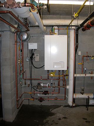
A central heating system provides warmth to a number of spaces within a building from one main source of heat. It is a component of heating, ventilation, and air conditioning systems, which can both cool and warm interior spaces.

<span class="mw-page-title-main">Damper (flow)</span> Valve or plate for regulating airflow inside a duct, chimney, vent, etc.

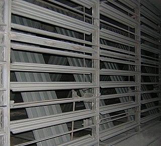
A damper is a valve or plate that stops or regulates the flow of air inside a duct, chimney, VAV box, air handler, or other air-handling equipment. A damper may be used to cut off central air conditioning to an unused room, or to regulate it for room-by-room temperature and climate control -- for example in the case of Volume Control Dampers. Its operation can be manual or automatic. Manual dampers are turned by a handle on the outside of a duct. Automatic dampers are used to regulate airflow constantly and are operated by electric or pneumatic motors, in turn controlled by a thermostat or building automation system. Automatic or motorized dampers may also be controlled by a solenoid, and the degree of air-flow calibrated, perhaps according to signals from the thermostat going to the actuator of the damper in order to modulate the flow of air-conditioned air in order to effect climate control.

<span class="mw-page-title-main">Hydronics</span> Use of liquid or gaseous water in heating or cooling systems

Hydronics is the use of liquid water or gaseous water (steam) or a water solution as heat-transfer medium in heating and cooling systems. The name differentiates such systems from oil and refrigerant systems.

<span class="mw-page-title-main">Air handler</span> Device used to regulate and circulate air as part of an HVAC system

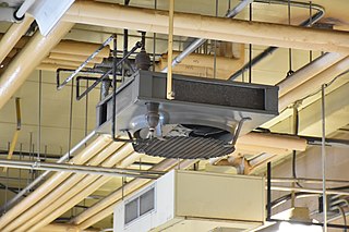
An air handler, or air handling unit, is a device used to regulate and circulate air as part of a heating, ventilating, and air-conditioning (HVAC) system. An air handler is usually a large metal box containing a blower, furnace or A/C elements, filter racks or chambers, sound attenuators, and dampers. Air handlers usually connect to a ductwork ventilation system that distributes the conditioned air through the building and returns it to the AHU. Sometimes AHUs discharge (supply) and admit (return) air directly to and from the space served without ductwork

A zone valve is a specific type of valve used to control the flow of water or steam in a hydronic heating or cooling system.

Variable air volume (VAV) is a type of heating, ventilating, and/or air-conditioning (HVAC) system. Unlike constant air volume (CAV) systems, which supply a constant airflow at a variable temperature, VAV systems vary the airflow at a constant or varying temperature. The advantages of VAV systems over constant-volume systems include more precise temperature control, reduced compressor wear, lower energy consumption by system fans, less fan noise, and additional passive dehumidification.

<span class="mw-page-title-main">Heater core</span>

A heater core is a radiator-like device used in heating the cabin of a vehicle. Hot coolant from the vehicle's engine is passed through a winding tube of the core, a heat exchanger between coolant and cabin air. Fins attached to the core tubes serve to increase surface area for heat transfer to air that is forced past them by a fan, thereby heating the passenger compartment.

<span class="mw-page-title-main">Wax thermostatic element</span>

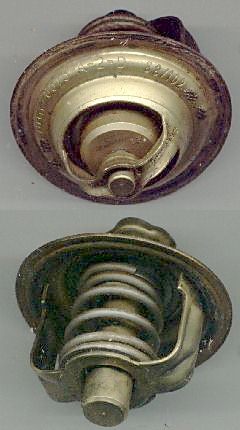
The wax thermostatic element was invented in 1934 by Sergius Vernet (1899–1968). Its principal application is in automotive thermostats used in the engine cooling system. The first applications in the plumbing and heating industries were in Sweden (1970) and in Switzerland (1971).

A chilled beam is a type of radiation/convection HVAC system designed to heat and cool large buildings through the use of water. This method removes most of the zone sensible local heat gains and allows the flow rate of pre-conditioned air from the air handling unit to be reduced, lowering by 60% to 80% the ducted design airflow rate and the equipment capacity requirements. There are two types of chilled beams, a Passive Chilled Beam (PCB) and an Active Chilled Beam (ACB). They both consist of pipes of water (fin-and-tube) that pass through a heat exchanger contained in a case suspended from, or recessed in, the ceiling. As the beam cools the air around it, the air becomes denser and falls to the floor. It is replaced by warmer air moving up from below, causing a constant passive air movement called convection, to cool the room. The active beam consists of air duct connections, induction nozzles, hydronic heat transfer coils, supply outlets and induced air inlets. It contains an integral air supply that passes through nozzles, and induces air from the room to the cooling coil. For this reason, it has a better cooling capacity than the passive beam. Instead, the passive beam provides space cooling without the use of a fan and it is mainly done by convection. Passive beams can be either exposed or recessed. The passive approach can provide higher thermal comfort levels, while the active approach uses the momentum of ventilation air that enters at relatively high velocity to induce the circulation of room air through the unit. A chilled beam is similar in appearance to a VRF unit.

<span class="mw-page-title-main">Fan coil unit</span> HVAC device

A fan coil unit (FCU), also known as a Vertical Fan Coil-Unit (VFC), is a device consisting of a heat exchanger (coil) and a fan. FCUs are commonly found in HVAC systems of residential, commercial, and industrial buildings that use ducted split air conditioning or with central plant cooling. FCUs are typically connected to ductwork and a thermostat to regulate the temperature of one or more spaces and to assist the main air handling unit for each space if used with chillers. The thermostat controls the fan speed and/or the flow of water or refrigerant to the heat exchanger using a control valve.

In heating, ventilation, and air conditioning (HVAC), testing, adjusting and balancing (TAB) are the three major steps used to achieve proper operation of heating, ventilation, and air conditioning systems. TAB usually refers to commercial building construction and the specialized contractors who employ personnel that perform this service.

<span class="mw-page-title-main">Components of jet engines</span> Brief description of components needed for jet engines

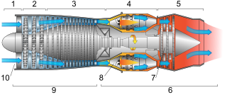
This article briefly describes the components and systems found in jet engines.

HVAC is a major sub discipline of mechanical engineering. The goal of HVAC design is to balance indoor environmental comfort with other factors such as installation cost, ease of maintenance, and energy efficiency. The discipline of HVAC includes a large number of specialized terms and acronyms, many of which are summarized in this glossary.

<span class="mw-page-title-main">Instrumentation in petrochemical industries</span>

Instrumentation is used to monitor and control the process plant in the oil, gas and petrochemical industries. Instrumentation ensures that the plant operates within defined parameters to produce materials of consistent quality and within the required specifications. It also ensures that the plant is operated safely and acts to correct out of tolerance operation and to automatically shut down the plant to prevent hazardous conditions from occurring. Instrumentation comprises sensor elements, signal transmitters, controllers, indicators and alarms, actuated valves, logic circuits and operator interfaces.

<span class="mw-page-title-main">Hydronic balancing</span>

Hydronic balancing, also called hydraulic balancing, is the process of optimizing the distribution of water in a building's hydronic heating or cooling system by equalizing the system pressure to provide the intended indoor climate at optimum energy efficiency and minimal operating cost.

<span class="mw-page-title-main">Dedicated outdoor air system</span>

A dedicated outdoor air system (DOAS) is a type of heating, ventilation and air-conditioning (HVAC) system that consists of two parallel systems: a dedicated system for delivering outdoor air ventilation that handles both the latent and sensible loads of conditioning the ventilation air, and a parallel system to handle the loads generated by indoor/process sources and those that pass through the building enclosure.

<span class="mw-page-title-main">Automobile air conditioning</span> System to cool the air in a vehicle

Automobile air conditioning systems use air conditioning to cool the air in a vehicle.

The Glossary of Geothermal Heating and Cooling provides definitions of many terms used within the Geothermal heat pump industry. The terms in this glossary may be used by industry professionals, for education materials, and by the general public.

References

  1. Julian de Bullet, "Variable Flow Chiller Plant Design" Archived 2014-04-16 at the Wayback Machine , ASHRAE, 2012.
  2. James J. Nonnenmann, "Chilled Water Plant Pumping Schemes" Archived 2013-05-20 at the Wayback Machine , PE (Page 11 of 17).
  3. Cooper, John (14 April 2006). "Automatic balancing is the key to efficient systems". MBS (Modern Building Systems).
  4. "Is a constant flow or variable flow system best?". Sagicofim Comfort. Retrieved 2022-10-04.
  5. "Crane Fluid Systems - Our Genius Is Valves". www.cranefs.com. Retrieved 2022-10-04.