Axonometry

Last updated
Cavalier projection of a semicircular archway. Axonometrie-torbogen-c.svg
Cavalier projection of a semicircular archway.

Axonometry is a graphical procedure belonging to descriptive geometry that generates a planar image of a three-dimensional object. The term "axonometry" means "to measure along axes", and indicates that the dimensions and scaling of the coordinate axes play a crucial role. The result of an axonometric procedure is a uniformly-scaled parallel projection of the object. In general, the resulting parallel projection is oblique (the rays are not perpendicular to the image plane); but in special cases the result is orthographic (the rays are perpendicular to the image plane), which in this context is called an orthogonal axonometry.

Contents

In technical drawing and in architecture, axonometric perspective is a form of two-dimensional representation of three-dimensional objects whose goal is to preserve the impression of volume or relief. Sometimes also called rapid perspective or artificial perspective, it differs from conical perspective and does not represent what the eye actually sees: in particular parallel lines remain parallel and distant objects are not reduced in size. It can be considered a conical perspective conique whose center has been pushed out to infinity, i.e. very far from the object observed.

The term axonometry is used both for the graphical procedure described below, as well as the image produced by this procedure.

Axonometry should not be confused with axonometric projection , which in English literature usually refers to orthogonal axonometry.

Principle of axonometry

The point
P
-
{\displaystyle {\overline {P}}}
is the projection of a point
P
=
(
x
,
y
,
z
)
{\displaystyle P=(x,y,z)}
onto the projection plane P. The foreshortenings are
v
x
{\displaystyle v_{x}}
,
v
y
{\displaystyle v_{y}}
and
v
z
{\displaystyle v_{z}}
. Axonom-def.svg
The point is the projection of a point onto the projection plane Π. The foreshortenings are , and .

Pohlke's theorem is the basis for the following procedure to construct a scaled parallel projection of a three-dimensional object: [1] [2]

  1. Select projections of the coordinate axes, such that all three coordinate axes are not collapsed to a single point or line. Usually the z-axis is vertical.
  2. Select for these projections the foreshortenings, , and , where
  3. The projection of a point is determined in three sub-steps (the result is independent of the order of these sub-steps):
    • starting at the point , move by the amount in the direction of , then
    • move by the amount in the direction of , then
    • move by the amount in the direction of and finally
  4. Mark the final position as point .

In order to obtain undistorted results, select the projections of the axes and foreshortenings carefully (see below). In order to produce an orthographic projection, only the projections of the coordinate axes are freely selected; the foreshortenings are fixed (see de:orthogonale Axonometrie). [3]

The choice of the images of the axes and the foreshortenings

Parameters and notations Axo-parameter-gen.svg
Parameters and notations

Notation:

The angles can be chosen so that
The foreshortenings:

Only for suitable choices of angles and foreshortenings does one get undistorted images. The next diagram shows the images of the unit cube for various angles and foreshortenings and gives some hints for how to make these personal choices.

Various axonometric images of a unit cube. (The image plane is parallel to the y-z-plane.)
The left and the far right images look more like prolonged cuboids instead of a cube. Axonometry-var14.svg
Various axonometric images of a unit cube. (The image plane is parallel to the y-z-plane.)
The left and the far right images look more like prolonged cuboids instead of a cube.
Axonometry (cavalier perspective) of a house on checked pattern paper. Haus-karo-axonometrie.svg
Axonometry (cavalier perspective) of a house on checked pattern paper.

In order to keep the drawing simple, one should choose simple foreshortenings, for example or .

If two foreshortenings are equal, the projection is called dimetric.
If the three foreshortenings are equal, the projection is called isometric.
If all foreshortenings are different, the projection is called trimetric.

The parameters in the diagram at right (e.g. of the house drawn on graph paper) are: Hence it is a dimetric axonometry. The image plane is parallel to the y-z-plane and any planar figure parallel to the y-z-plane appears in its true shape.

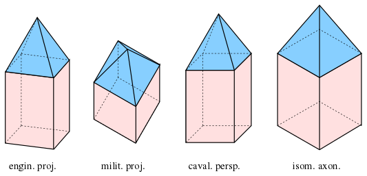
Special axonometries

Commonly used projections and perspectives with angles between the transformed coordinate axes (α, β, γ), angles from the horizon (αh, βh, without γh = 90°) and scaling factors (vi)
Name or propertyα = ∠x̄z̄β = ∠ȳz̄γ = ∠x̄ȳαhβhvxvyvzv
Orthogonal, orthographic, planar90°270°270°v0%any
Trimetric90° + αh90° + βh360° − α − βanyanyanyanyanyany
Dimetricv
Isometricv
Normal100%
Oblique, clinographic< 90°< 90°anyanyanytan(αh)
Symmetricα360° − 2·α< 90°αhany
Equiangular120°30°
Normal, 1:1 isometricv100%
Standard, shortened isometric ≈ 81%
Pixel, 1:2 isometric116.6°126.9°arctan(v)50%
Engineering131.4°97.2°131.4°arccos(3/4)arcsin(1/8)50%v100%
Cavalier90° + αh90°270° − αanyany
Cabinet, dimetric cavalier< 100%
Standard, isometric cavalier135°135°45°v
Standard 1:2 cabinet50%v
30° cabinet116.6°153.4°arctan(vx)
60° cabinet153.4°116.6°arccot(vx)
30° cavalier120°150°30°any
Aerial, bird's eye view135°90°45°vany100%
Militaryv
Planometric90° + αh180° − αhany90° − αhany
Normal planometric100%
Shortened planometric2/3 ≈ 67%
Parameters of special axonometries. Axo-parameter-spec.svg
Parameters of special axonometries.

Engineer projection

In this case [4] [5]

These angles are marked on many German set squares.

Advantages of an engineer projection:

For more details: see de:Axonometrie.

Cavalier perspective, cabinet perspective

In the literature the terms "cavalier perspective" and "cabinet perspective" are not uniformly defined. The above definition is the most general one. Often, further restrictions are applied. [6] [7] For example:

cabinet perspective: additionally choose (oblique) and (dimetric),
cavalier perspective: additionally choose (oblique) and (isometric).

Birds eye view, military projection

military projection: additionally choose (isometric).

Such axonometries are often used for city maps, in order to keep horizontal figures undistorted.

Isometric axonometry

standard isometry: cube, cuboid, house and sphere Axo-iso-beisp.svg
standard isometry: cube, cuboid, house and sphere

(Not to be confused with an isometry between metric spaces.)

For an isometric axonometry all foreshortenings are equal. The angles can be chosen arbitrarily, but a common choice is .

For the standard isometry or just isometry one chooses:

The advantage of a standard isometry:

In order to prevent scaling, one can choose the unhandy foreshortenings

and the image is an (unscaled) orthographic projection.

various axonometries of a tower
dimetric military projection:
v
z
=
0.5
,
v
x
,
y
=
1
{\displaystyle v_{z}=0.5,v_{x,y}=1}
, dimetric engineering and cavalier projections:
v
x
=
0.5
,
v
y
,
z
=
1
{\displaystyle v_{x}=0.5,v_{y,z}=1}
, isometric axonometry:
v
x
,
y
,
z
=
1
{\displaystyle v_{x,y,z}=1} Axo-examples.svg
various axonometries of a tower
dimetric military projection: , dimetric engineering and cavalier projections: , isometric axonometry:

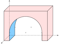
Circles in axonometry

A parallel projection of a circle is in general an ellipse. An important special case occurs, if the circle's plane is parallel to the image planethe image of the circle is then a congruent circle. In the diagram, the circle contained in the front face is undistorted. If the image of a circle is an ellipse, one can map four points on orthogonal diameters and the surrounding square of tangents and in the image parallelogram fill-in an ellipse by hand. A better, but more time consuming method consists of drawing the images of two perpendicular diameters of the circle, which are conjugate diameters of the image ellipse, determining the axes of the ellipse with Rytz's construction and drawing the ellipse.

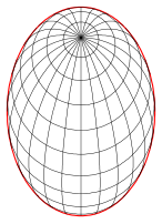
Spheres in axonometry

In a general axonometry of a sphere the image contour is an ellipse. The contour of a sphere is a circle only in an orthogonal axonometry. But, as the engineer projection and the standard isometry are scaled orthographic projections, the contour of a sphere is a circle in these cases, as well. As the diagram shows, an ellipse as the contour of a sphere might be confusing, so, if a sphere is part of an object to be mapped, one should choose an orthogonal axonometry or an engineer projection or a standard isometry.

Related Research Articles

<span class="mw-page-title-main">Ellipse</span> Plane curve: conic section

In mathematics, an ellipse is a plane curve surrounding two focal points, such that for all points on the curve, the sum of the two distances to the focal points is a constant. It generalizes a circle, which is the special type of ellipse in which the two focal points are the same. The elongation of an ellipse is measured by its eccentricity , a number ranging from to .

<span class="mw-page-title-main">Hyperbola</span> Plane curve: conic section

In mathematics, a hyperbola is a type of smooth curve lying in a plane, defined by its geometric properties or by equations for which it is the solution set. A hyperbola has two pieces, called connected components or branches, that are mirror images of each other and resemble two infinite bows. The hyperbola is one of the three kinds of conic section, formed by the intersection of a plane and a double cone. If the plane intersects both halves of the double cone but does not pass through the apex of the cones, then the conic is a hyperbola.

<span class="mw-page-title-main">Similarity (geometry)</span> Property of objects which are scaled or mirrored versions of each other

In Euclidean geometry, two objects are similar if they have the same shape, or if one has the same shape as the mirror image of the other. More precisely, one can be obtained from the other by uniformly scaling, possibly with additional translation, rotation and reflection. This means that either object can be rescaled, repositioned, and reflected, so as to coincide precisely with the other object. If two objects are similar, each is congruent to the result of a particular uniform scaling of the other.

<span class="mw-page-title-main">Ellipsoid</span> Quadric surface that looks like a deformed sphere

An ellipsoid is a surface that can be obtained from a sphere by deforming it by means of directional scalings, or more generally, of an affine transformation.

<span class="mw-page-title-main">Isometric projection</span> Method for visually representing three-dimensional objects

Isometric projection is a method for visually representing three-dimensional objects in two dimensions in technical and engineering drawings. It is an axonometric projection in which the three coordinate axes appear equally foreshortened and the angle between any two of them is 120 degrees.

In mechanics and geometry, the 3D rotation group, often denoted SO(3), is the group of all rotations about the origin of three-dimensional Euclidean space under the operation of composition.

<span class="mw-page-title-main">Orthographic projection</span> Means of projecting three-dimensional objects in two dimensions

Orthographic projection is a means of representing three-dimensional objects in two dimensions. Orthographic projection is a form of parallel projection in which all the projection lines are orthogonal to the projection plane, resulting in every plane of the scene appearing in affine transformation on the viewing surface. The obverse of an orthographic projection is an oblique projection, which is a parallel projection in which the projection lines are not orthogonal to the projection plane.

<span class="mw-page-title-main">3D projection</span> Design technique

A 3D projection is a design technique used to display a three-dimensional (3D) object on a two-dimensional (2D) surface. These projections rely on visual perspective and aspect analysis to project a complex object for viewing capability on a simpler plane.

<span class="mw-page-title-main">Axonometric projection</span> Type of orthographic projection

Axonometric projection is a type of orthographic projection used for creating a pictorial drawing of an object, where the object is rotated around one or more of its axes to reveal multiple sides.

<span class="mw-page-title-main">Oblique projection</span> Type of technical drawing

Oblique projection is a simple type of technical drawing of graphical projection used for producing two-dimensional (2D) images of three-dimensional (3D) objects.

<span class="mw-page-title-main">Curvilinear perspective</span>

Curvilinear perspective, also five-point perspective, is a graphical projection used to draw 3D objects on 2D surfaces. It was formally codified in 1968 by the artists and art historians André Barre and Albert Flocon in the book La Perspective curviligne, which was translated into English in 1987 as Curvilinear Perspective: From Visual Space to the Constructed Image and published by the University of California Press.

<span class="mw-page-title-main">Vanishing point</span> Artistic concept relating to perspective

A vanishing point is a point on the image plane of a perspective rendering where the two-dimensional perspective projections of mutually parallel lines in three-dimensional space appear to converge. When the set of parallel lines is perpendicular to a picture plane, the construction is known as one-point perspective, and their vanishing point corresponds to the oculus, or "eye point", from which the image should be viewed for correct perspective geometry. Traditional linear drawings use objects with one to three sets of parallels, defining one to three vanishing points.

In linear algebra, a rotation matrix is a transformation matrix that is used to perform a rotation in Euclidean space. For example, using the convention below, the matrix

<span class="mw-page-title-main">Cross section (geometry)</span> Geometrical concept

In geometry and science, a cross section is the non-empty intersection of a solid body in three-dimensional space with a plane, or the analog in higher-dimensional spaces. Cutting an object into slices creates many parallel cross-sections. The boundary of a cross-section in three-dimensional space that is parallel to two of the axes, that is, parallel to the plane determined by these axes, is sometimes referred to as a contour line; for example, if a plane cuts through mountains of a raised-relief map parallel to the ground, the result is a contour line in two-dimensional space showing points on the surface of the mountains of equal elevation.

<span class="mw-page-title-main">Scale (map)</span> Ratio of distance on a map to the corresponding distance on the ground

The scale of a map is the ratio of a distance on the map to the corresponding distance on the ground. This simple concept is complicated by the curvature of the Earth's surface, which forces scale to vary across a map. Because of this variation, the concept of scale becomes meaningful in two distinct ways.

In geometry, a Euclidean plane isometry is an isometry of the Euclidean plane, or more informally, a way of transforming the plane that preserves geometrical properties such as length. There are four types: translations, rotations, reflections, and glide reflections.

<span class="mw-page-title-main">Parallel projection</span> Projection of a 3D object onto a plane via parallel rays

In three-dimensional geometry, a parallel projection is a projection of an object in three-dimensional space onto a fixed plane, known as the projection plane or image plane, where the rays, known as lines of sight or projection lines, are parallel to each other. It is a basic tool in descriptive geometry. The projection is called orthographic if the rays are perpendicular (orthogonal) to the image plane, and oblique or skew if they are not.

<span class="mw-page-title-main">Homothetic center</span> Point from which two similar geometric figures can be scaled to each other

In geometry, a homothetic center is a point from which at least two geometrically similar figures can be seen as a dilation or contraction of one another. If the center is external, the two figures are directly similar to one another; their angles have the same rotational sense. If the center is internal, the two figures are scaled mirror images of one another; their angles have the opposite sense.

<span class="mw-page-title-main">Rytz's construction</span> Method of finding axes and veritces of an ellipse

The Rytz’s axis construction is a basic method of descriptive geometry to find the axes, the semi-major axis and semi-minor axis and the vertices of an ellipse, starting from two conjugated half-diameters. If the center and the semi axis of an ellipse are determined the ellipse can be drawn using an ellipsograph or by hand.

Pohlke's theorem is the fundamental theorem of axonometry. It was established 1853 by the German painter and teacher of descriptive geometry Karl Wilhelm Pohlke. The first proof of the theorem was published 1864 by the German mathematician Hermann Amandus Schwarz, who was a student of Pohlke. Therefore the theorem is sometimes called theorem of Pohlke and Schwarz, too.

References

Notes
  1. Graf 1961, p. 144.
  2. Stärk 1978, p. 156.
  3. Graf 1961, p. 145.
  4. Graf 1961, p. 155.
  5. Stärk 1978, p. 168.
  6. Graf 1961, p. 95.
  7. Stärk 1978, p. 159.