Axonometric projection

Last updated

Axonometric projection is a type of orthographic projection used for creating a pictorial drawing of an object, where the object is rotated around one or more of its axes to reveal multiple sides. [1]

Contents

Overview

Classification of Axonometric projection and some 3D projections Comparison of graphical projections.svg
Classification of Axonometric projection and some 3D projections

"Axonometry" means "to measure along the axes". In German literature, axonometry is based on Pohlke's theorem, such that the scope of axonometric projection could encompass every type of parallel projection, including not only orthographic projection (and multiview projection), but also oblique projection. However, outside of German literature, the term "axonometric" is sometimes used only to distinguish between orthographic views where the principal axes of an object are not orthogonal to the projection plane, and orthographic views in which the principal axes of the object are orthogonal to the projection plane. (In multiview projection these would be called auxiliary views and primary views, respectively.) Confusingly, the term "orthographic projection" is also sometimes reserved only for the primary views.

Thus, in German literature, "axonometric projection" might be considered synonymous with "parallel projection", overall; but in English literature, an "axonometric projection" might be considered synonymous with an "auxiliary view" (versus a "primary view") in a "multiview orthographic projection".

With an axonometric projection, the scale of an object does not depend on its location (i.e., an object in the "foreground" has the same scale as an object in the "background"); consequently, such pictures look distorted, as human vision and photography use perspective projection, in which the perceived scale of an object depends on its distance and location from the viewer. This distortion, the direct result of a presence or absence of foreshortening, is especially evident if the object is mostly composed of rectangular features. Despite this limitation, axonometric projection can be useful for purposes of illustration, especially because it allows for simultaneously relaying precise measurements.

Three types

Comparison of several types of graphical projection Graphical projection comparison.png
Comparison of several types of graphical projection
Various projections and how they are produced Various projections of cube above plane.svg
Various projections and how they are produced
The three axonometric views. The percentages show the amount of foreshortening. Axonometric projections.png
The three axonometric views. The percentages show the amount of foreshortening.

The three types of axonometric projection are isometric projection , dimetric projection, and trimetric projection, depending on the exact angle by which the view deviates from the orthogonal. [2] [3] Typically in axonometric drawing, as in other types of pictorials, one axis of space is shown to be vertical.

In isometric projection, the most commonly used form of axonometric projection in engineering drawing, [4] the direction of viewing is such that the three axes of space appear equally foreshortened, and there is a common angle of 120° between them. As the distortion caused by foreshortening is uniform, the proportionality between lengths is preserved, and the axes share a common scale; this eases one's ability to take measurements directly from the drawing. Another advantage is that 120° angles are easily constructed using only a compass and straightedge.

In dimetric projection, the direction of viewing is such that two of the three axes of space appear equally foreshortened, of which the attendant scale and angles of presentation are determined according to the angle of viewing; the scale of the third direction is determined separately. Dimensional approximations are common in dimetric drawings.[ clarification needed ]

In trimetric projection, the direction of viewing is such that all of the three axes of space appear unequally foreshortened. The scale along each of the three axes and the angles among them are determined separately as dictated by the angle of viewing. Dimensional approximations in trimetric drawings are common,[ clarification needed ] and trimetric perspective is seldom used in technical drawings. [3]

History

Axonometry originated in China. [5] Unlike the linear perspective in European art whose perspective was objective, or looking from the outside, Chinese art used parallel projections within the painting that allowed the viewer to consider both the space and the ongoing progression of time in one scroll. [6] The concept of isometry had existed in a rough empirical form for centuries, well before Professor William Farish (1759–1837) of Cambridge University was the first to provide detailed rules for isometric drawing. [7] [8]

Farish published his ideas in the 1822 paper "On Isometric Perspective", in which he recognized the "need for accurate technical working drawings free of optical distortion. This would lead him to formulate isometry. Isometry means "equal measures" because the same scale is used for height, width, and depth". [9]

From the middle of the 19th century, according to Jan Krikke (2006) [9] isometry became an "invaluable tool for engineers, and soon thereafter axonometry and isometry were incorporated in the curriculum of architectural training courses in Europe and the U.S. The popular acceptance of axonometry came in the 1920s, when modernist architects from the Bauhaus and De Stijl embraced it". [9] De Stijl architects like Theo van Doesburg used axonometry for their architectural designs, which caused a sensation when exhibited in Paris in 1923". [9]

Since the 1920s axonometry, or parallel perspective, has provided an important graphic technique for artists, architects, and engineers. Like linear perspective, axonometry helps depict three-dimensional space on a two-dimensional picture plane. It usually comes as a standard feature of CAD systems and other visual computing tools. [6] According to science author and Medium journalist Jan Krikke, axonometry, and the pictorial grammar that goes with it, has taken on a new significance with the introduction of visual computing and engineering drawing. [6] [5] [10] [11]

Limitations

IsometricFlaw 2.svg
In this drawing, the blue sphere is two units higher than the red one. However, this difference in elevation is not apparent if one covers the right half of the picture.
Impossible staircase.svg
The Penrose stairs depicts a staircase which seems to ascend (anticlockwise) or descend (clockwise) yet forms a continuous loop.

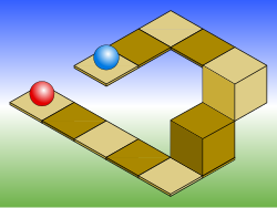
As with other types of parallel projection, objects drawn with axonometric projection do not appear larger or smaller as they lie closer to or farther away from the viewer. While advantageous for architectural drawings, where measurements must be taken directly from the image, the result is a perceived distortion, since unlike perspective projection, this is not how human vision or photography normally works. It also can easily result in situations where depth and altitude are difficult to gauge, as is shown in the illustration to the right.

This visual ambiguity has been exploited in optical art, as well as "impossible object" drawings. Though not strictly axonometric, M. C. Escher's Waterfall (1961) is a well-known image, in which a channel of water seems to travel unaided along a downward path, only to then paradoxically fall once again as it returns to its source. The water thus appears to disobey the law of conservation of energy.

Related Research Articles

<span class="mw-page-title-main">Technical drawing</span> Creation of standards and the technical drawings

Technical drawing, drafting or drawing, is the act and discipline of composing drawings that visually communicate how something functions or is constructed.

<span class="mw-page-title-main">Isometric projection</span> Method for visually representing three-dimensional objects

Isometric projection is a method for visually representing three-dimensional objects in two dimensions in technical and engineering drawings. It is an axonometric projection in which the three coordinate axes appear equally foreshortened and the angle between any two of them is 120 degrees.

<span class="mw-page-title-main">Engineering drawing</span> Type of technical drawing used to define requirements for engineered items

An engineering drawing is a type of technical drawing that is used to convey information about an object. A common use is to specify the geometry necessary for the construction of a component and is called a detail drawing. Usually, a number of drawings are necessary to completely specify even a simple component. These drawings are linked together by a "master drawing." This "master drawing" is more commonly known as an assembly drawing. The assembly drawing gives the drawing numbers of the subsequent detailed components, quantities required, construction materials and possibly 3D images that can be used to locate individual items. Although mostly consisting of pictographic representations, abbreviations and symbols are used for brevity and additional textual explanations may also be provided to convey the necessary information.

<span class="mw-page-title-main">Orthographic projection</span> Means of projecting three-dimensional objects in two dimensions

Orthographic projection is a means of representing three-dimensional objects in two dimensions. Orthographic projection is a form of parallel projection in which all the projection lines are orthogonal to the projection plane, resulting in every plane of the scene appearing in affine transformation on the viewing surface. The obverse of an orthographic projection is an oblique projection, which is a parallel projection in which the projection lines are not orthogonal to the projection plane.

<span class="mw-page-title-main">3D projection</span> Design technique

A 3D projection is a design technique used to display a three-dimensional (3D) object on a two-dimensional (2D) surface. These projections rely on visual perspective and aspect analysis to project a complex object for viewing capability on a simpler plane.

<span class="mw-page-title-main">Perspective (graphical)</span> Form of graphical projection where the projection lines converge to one or more points

Linear or point-projection perspective is one of two types of graphical projection perspective in the graphic arts; the other is parallel projection. Linear perspective is an approximate representation, generally on a flat surface, of an image as it is seen by the eye. Perspective drawing is useful for representing a three-dimensional scene in a two-dimensional medium, like paper.

<span class="mw-page-title-main">Descriptive geometry</span> Branch of geometry which allows the representation of three-dimensional objects in two dimensions

Descriptive geometry is the branch of geometry which allows the representation of three-dimensional objects in two dimensions by using a specific set of procedures. The resulting techniques are important for engineering, architecture, design and in art. The theoretical basis for descriptive geometry is provided by planar geometric projections. The earliest known publication on the technique was "Underweysung der Messung mit dem Zirckel und Richtscheyt", published in Linien, Nuremberg: 1525, by Albrecht Dürer. Italian architect Guarino Guarini was also a pioneer of projective and descriptive geometry, as is clear from his Placita Philosophica (1665), Euclides Adauctus (1671) and Architettura Civile, anticipating the work of Gaspard Monge (1746–1818), who is usually credited with the invention of descriptive geometry. Gaspard Monge is usually considered the "father of descriptive geometry" due to his developments in geometric problem solving. His first discoveries were in 1765 while he was working as a draftsman for military fortifications, although his findings were published later on.

<span class="mw-page-title-main">Oblique projection</span> Type of technical drawing

Oblique projection is a simple type of technical drawing of graphical projection used for producing two-dimensional (2D) images of three-dimensional (3D) objects.

2.5D perspective refers to gameplay or movement in a video game or virtual reality environment that is restricted to a two-dimensional (2D) plane with little or no access to a third dimension in a space that otherwise appears to be three-dimensional and is often simulated and rendered in a 3D digital environment.

<span class="mw-page-title-main">Cross section (geometry)</span> Geometrical concept

In geometry and science, a cross section is the non-empty intersection of a solid body in three-dimensional space with a plane, or the analog in higher-dimensional spaces. Cutting an object into slices creates many parallel cross-sections. The boundary of a cross-section in three-dimensional space that is parallel to two of the axes, that is, parallel to the plane determined by these axes, is sometimes referred to as a contour line; for example, if a plane cuts through mountains of a raised-relief map parallel to the ground, the result is a contour line in two-dimensional space showing points on the surface of the mountains of equal elevation.

<span class="mw-page-title-main">Parallel projection</span> Projection of a 3D object onto a plane via parallel rays

In three-dimensional geometry, a parallel projection is a projection of an object in three-dimensional space onto a fixed plane, known as the projection plane or image plane, where the rays, known as lines of sight or projection lines, are parallel to each other. It is a basic tool in descriptive geometry. The projection is called orthographic if the rays are perpendicular (orthogonal) to the image plane, and oblique or skew if they are not.

<span class="mw-page-title-main">Technical illustration</span> Process of visually communicating technical concepts or subjects

Technical illustration is illustration meant to visually communicate information of a technical nature. Technical illustrations can be components of technical drawings or diagrams. Technical illustrations in general aim "to generate expressive images that effectively convey certain information via the visual channel to the human observer".

<span class="mw-page-title-main">Plan (drawing)</span>

Plans are a set of drawings or two-dimensional diagrams used to describe a place or object, or to communicate building or fabrication instructions. Usually plans are drawn or printed on paper, but they can take the form of a digital file.

<span class="mw-page-title-main">William Farish (chemist)</span> British chemist

William Farish (1759–1837) was a British scientist who was a professor of Chemistry and Natural Philosophy at the University of Cambridge, known for the development of the method of isometric projection and development of the first written university examination.

<span class="mw-page-title-main">Multiview orthographic projection</span> Technique of illustration

In technical drawing and computer graphics, a multiview projection is a technique of illustration by which a standardized series of orthographic two-dimensional pictures are constructed to represent the form of a three-dimensional object. Up to six pictures of an object are produced, with each projection plane parallel to one of the coordinate axes of the object. The views are positioned relative to each other according to either of two schemes: first-angle or third-angle projection. In each, the appearances of views may be thought of as being projected onto planes that form a six-sided box around the object. Although six different sides can be drawn, usually three views of a drawing give enough information to make a three-dimensional object.

<span class="mw-page-title-main">Architectural drawing</span> Technical drawing of a building (or building project)

An architectural drawing or architect's drawing is a technical drawing of a building that falls within the definition of architecture. Architectural drawings are used by architects and others for a number of purposes: to develop a design idea into a coherent proposal, to communicate ideas and concepts, to convince clients of the merits of a design, to assist a building contractor to construct it based on design intent, as a record of the design and planned development, or to make a record of a building that already exists.

<span class="mw-page-title-main">Isometric video game graphics</span> Type of video game graphics

Isometric video game graphics are graphics employed in video games and pixel art that use a parallel projection, but which angle the viewpoint to reveal facets of the environment that would otherwise not be visible from a top-down perspective or side view, thereby producing a three-dimensional (3D) effect. Despite the name, isometric computer graphics are not necessarily truly isometric—i.e., the x, y, and z axes are not necessarily oriented 120° to each other. Instead, a variety of angles are used, with dimetric projection and a 2:1 pixel ratio being the most common. The terms "3/4 perspective", "3/4 view", "2.5D", and "pseudo 3D" are also sometimes used, although these terms can bear slightly different meanings in other contexts.

The term isometric comes from the Greek for "having equal measurement".

<span class="mw-page-title-main">Axonometry</span> The process of projecting a three-dimensional object onto a two-dimensional plane

Axonometry is a graphical procedure belonging to descriptive geometry that generates a planar image of a three-dimensional object. The term "axonometry" means "to measure along axes", and indicates that the dimensions and scaling of the coordinate axes play a crucial role. The result of an axonometric procedure is a uniformly-scaled parallel projection of the object. In general, the resulting parallel projection is oblique ; but in special cases the result is orthographic, which in this context is called an orthogonal axonometry.

References

  1. Gary R. Bertoline et al. (2002) Technical Graphics Communication. McGraw–Hill Professional, 2002. ISBN   0-07-365598-8, p. 330.
  2. Maynard, Patric (2005). Drawing distinctions: the varieties of graphic expression. Cornell University Press. p. 22. ISBN   0-8014-7280-6.
  3. 1 2 McReynolds, Tom; David Blythe (2005). Advanced graphics programming using openGL. Elsevier. p. 502. ISBN   1-55860-659-9.
  4. Godse, A. P. (1984). Computer graphics. Technical Publications. p. 29. ISBN   81-8431-558-9.[ permanent dead link ]
  5. 1 2 Krikke, Jan (2018-01-02). "Why the world relies on a Chinese "perspective"".
  6. 1 2 3 Jan Krikke (2000). "Axonometry: a matter of perspective". In: Computer Graphics and Applications, IEEE Jul/Aug 2000. Vol 20 (4), pp. 7–11.
  7. Barclay G. Jones (1986). Protecting historic architecture and museum collections from natural disasters. University of Michigan. ISBN   0-409-90035-4. p. 243.
  8. Charles Edmund Moorhouse (1974). Visual messages: graphic communication for senior students.
  9. 1 2 3 4 J. Krikke (1996). "A Chinese perspective for cyberspace? Archived 2009-06-01 at the Wayback Machine ". In: International Institute for Asian Studies Newsletter, 9, Summer 1996.
  10. Krikke, J. (July 2000). "Axonometry: A Matter of Perspective". IEEE Computer Graphics and Applications. 20 (4): 7–11. doi:10.1109/38.851742.
  11. "A Chinese Perspective for Cyberspace".
  12. William Farish (1822) "On Isometrical Perspective". In: Cambridge Philosophical Transactions. 1 (1822).

Further reading