
An electrical network is an interconnection of electrical components or a model of such an interconnection, consisting of electrical elements. An electrical circuit is a network consisting of a closed loop, giving a return path for the current. Thus all circuits are networks, but not all networks are circuits. Linear electrical networks, a special type consisting only of sources, linear lumped elements, and linear distributed elements, have the property that signals are linearly superimposable. They are thus more easily analyzed, using powerful frequency domain methods such as Laplace transforms, to determine DC response, AC response, and transient response.

An amplifier, electronic amplifier or (informally) amp is an electronic device that can increase the magnitude of a signal. It is a two-port electronic circuit that uses electric power from a power supply to increase the amplitude of a signal applied to its input terminals, producing a proportionally greater amplitude signal at its output. The amount of amplification provided by an amplifier is measured by its gain: the ratio of output voltage, current, or power to input. An amplifier is defined as a circuit that has a power gain greater than one.
In electrical engineering, the power factor of an AC power system is defined as the ratio of the real power absorbed by the load to the apparent power flowing in the circuit. Real power is the average of the instantaneous product of voltage and current and represents the capacity of the electricity for performing work. Apparent power is the product of root mean square (RMS) current and voltage. Due to energy stored in the load and returned to the source, or due to a non-linear load that distorts the wave shape of the current drawn from the source, the apparent power may be greater than the real power, so more current flows in the circuit than would be required to transfer real power alone. A power factor magnitude of less than one indicates the voltage and current are not in phase, reducing the average product of the two. A negative power factor occurs when the device generates real power, which then flows back towards the source.
In electrical engineering, electrical elements are conceptual abstractions representing idealized electrical components, such as resistors, capacitors, and inductors, used in the analysis of electrical networks. All electrical networks can be analyzed as multiple electrical elements interconnected by wires. Where the elements roughly correspond to real components, the representation can be in the form of a schematic diagram or circuit diagram. This is called a lumped-element circuit model. In other cases, infinitesimal elements are used to model the network in a distributed-element model.

A negative-feedback amplifier is an electronic amplifier that subtracts a fraction of its output from its input, so that negative feedback opposes the original signal. The applied negative feedback can improve its performance and reduces sensitivity to parameter variations due to manufacturing or environment. Because of these advantages, many amplifiers and control systems use negative feedback.

A power supply is an electrical device that supplies electric power to an electrical load. The main purpose of a power supply is to convert electric current from a source to the correct voltage, current, and frequency to power the load. As a result, power supplies are sometimes referred to as electric power converters. Some power supplies are separate standalone pieces of equipment, while others are built into the load appliances that they power. Examples of the latter include power supplies found in desktop computers and consumer electronics devices. Other functions that power supplies may perform include limiting the current drawn by the load to safe levels, shutting off the current in the event of an electrical fault, power conditioning to prevent electronic noise or voltage surges on the input from reaching the load, power-factor correction, and storing energy so it can continue to power the load in the event of a temporary interruption in the source power.

In electronics, negative resistance (NR) is a property of some electrical circuits and devices in which an increase in voltage across the device's terminals results in a decrease in electric current through it.
In power engineering, the power-flow study, or load-flow study, is a numerical analysis of the flow of electric power in an interconnected system. A power-flow study usually uses simplified notations such as a one-line diagram and per-unit system, and focuses on various aspects of AC power parameters, such as voltages, voltage angles, real power and reactive power. It analyzes the power systems in normal steady-state operation.
In electrical engineering and electronics, a network is a collection of interconnected components. Network analysis is the process of finding the voltages across, and the currents through, all network components. There are many techniques for calculating these values; however, for the most part, the techniques assume linear components. Except where stated, the methods described in this article are applicable only to linear network analysis.

A current source is an electronic circuit that delivers or absorbs an electric current which is independent of the voltage across it.
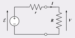
In electrical engineering, a practical electric power source which is a linear circuit may, according to Thévenin's theorem, be represented as an ideal voltage source in series with an impedance. This impedance is termed the internal resistance of the source. When the power source delivers current, the measured voltage output is lower than the no-load voltage; the difference is the voltage drop caused by the internal resistance. The concept of internal resistance applies to all kinds of electrical sources and is useful for analyzing many types of circuits.
In electrical engineering, an equivalent circuit refers to a theoretical circuit that retains all of the electrical characteristics of a given circuit. Often, an equivalent circuit is sought that simplifies calculation, and more broadly, that is a simplest form of a more complex circuit in order to aid analysis. In its most common form, an equivalent circuit is made up of linear, passive elements. However, more complex equivalent circuits are used that approximate the nonlinear behavior of the original circuit as well. These more complex circuits often are called macromodels of the original circuit. An example of a macromodel is the Boyle circuit for the 741 operational amplifier.
Small-signal modeling is a common analysis technique in electronics engineering used to approximate the behavior of electronic circuits containing nonlinear devices with linear equations. It is applicable to electronic circuits in which the AC signals are small relative to the DC bias currents and voltages. A small-signal model is an AC equivalent circuit in which the nonlinear circuit elements are replaced by linear elements whose values are given by the first-order (linear) approximation of their characteristic curve near the bias point.
The superposition theorem is a derived result of the superposition principle suited to the network analysis of electrical circuits. The superposition theorem states that for a linear system the response in any branch of a bilateral linear circuit having more than one independent source equals the algebraic sum of the responses caused by each independent source acting alone, where all the other independent sources are replaced by their internal impedances.
A linear circuit is an electronic circuit which obeys the superposition principle. This means that the output of the circuit F(x) when a linear combination of signals ax1(t) + bx2(t) is applied to it is equal to the linear combination of the outputs due to the signals x1(t) and x2(t) applied separately:

In electronics, biasing is the setting of DC operating conditions of an electronic component that processes time-varying signals. Many electronic devices, such as diodes, transistors and vacuum tubes, whose function is processing time-varying (AC) signals, also require a steady (DC) current or voltage at their terminals to operate correctly. This current or voltage is called bias. The AC signal applied to them is superposed on this DC bias current or voltage.
In the field of EMC, active EMI reduction refers to techniques aimed to reduce or to filter electromagnetic noise (EMI) making use of active electronic components. Active EMI reduction contrasts with passive filtering techniques, such as RC filters, LC filters RLC filters, which includes only passive electrical components. Hybrid solutions including both active and passive elements exist. Standards concerning conducted and radiated emissions published by IEC and FCC set the maximum noise level allowed for different classes of electrical devices. The frequency range of interest spans from 150 kHz to 30 MHz for conducted emissions and from 30 MHz to 40 GHz for radiated emissions. Meeting these requirements and guaranteeing the functionality of an electrical apparatus subject to electromagnetic interference are the main reason to include an EMI filter. In an electrical system, power converters, i.e. DC/DC converters, inverters and rectifiers, are the major sources of conducted EMI, due to their high-frequency switching ratio which gives rise to unwanted fast current and voltage transients. Since power electronics is nowadays spread in many fields, from power industrial application to automotive industry, EMI filtering has become necessary. In other fields, such as the telecommunication industry where the major focus is on radiated emissions, other techniques have been developed for EMI reduction, such as spread spectrum clocking which makes use of digital electronics, or electromagnetic shielding.
Passivity is a property of engineering systems, most commonly encountered in analog electronics and control systems. Typically, analog designers use passivity to refer to incrementally passive components and systems, which are incapable of power gain. In contrast, control systems engineers will use passivity to refer to thermodynamically passive ones, which consume, but do not produce, energy. As such, without context or a qualifier, the term passive is ambiguous.
Mechanical–electrical analogies are the representation of mechanical systems as electrical networks. At first, such analogies were used in reverse to help explain electrical phenomena in familiar mechanical terms. James Clerk Maxwell introduced analogies of this sort in the 19th century. However, as electrical network analysis matured it was found that certain mechanical problems could more easily be solved through an electrical analogy. Theoretical developments in the electrical domain that were particularly useful were the representation of an electrical network as an abstract topological diagram using the lumped element model and the ability of network analysis to synthesise a network to meet a prescribed frequency function.
This glossary of electrical and electronics engineering is a list of definitions of terms and concepts related specifically to electrical engineering and electronics engineering. For terms related to engineering in general, see Glossary of engineering.
