In object-oriented programming, a class defines the shared aspects of objects created from the class. The capabilities of a class differ between programming languages, but generally the shared aspects consist of state (variables) and behavior (methods) that are each either associated with a particular object or with all objects of that class.
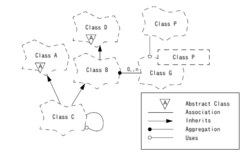
An object-modeling language is a standardized set of symbols used to model a software system using an object-oriented framework. The symbols can be either informal or formal ranging from predefined graphical templates to formal object models defined by grammars and specifications.

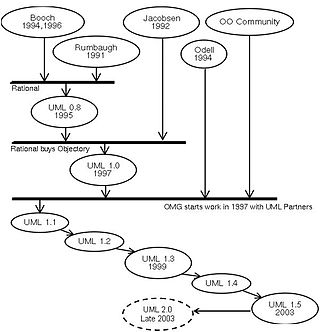
The unified modeling language (UML) is a general-purpose visual modeling language that is intended to provide a standard way to visualize the design of a system.
In software engineering, a design pattern describes a relatively small, well-defined aspect of a computer program in terms of how to write the code.
In software development, an object is an entity that has state, behavior, and identity. An object can model some part of reality or can be an invention of the design process whose collaborations with other such objects serve as the mechanisms that provide some higher-level behavior. Put another way, an object represents an individual, identifiable item, unit, or entity, either real or abstract, with a well-defined role in the problem domain.

The object-modeling technique (OMT) is an object modeling approach for software modeling and designing. It was developed around 1991 by Rumbaugh, Blaha, Premerlani, Eddy and Lorensen as a method to develop object-oriented systems and to support object-oriented programming. OMT describes object model or static structure of the system.
The rational unified process (RUP) is an iterative software development process framework created by the Rational Software Corporation, a division of IBM since 2003. RUP is not a single concrete prescriptive process, but rather an adaptable process framework, intended to be tailored by the development organizations and software project teams that will select the elements of the process that are appropriate for their needs. RUP is a specific implementation of the Unified Process.
In software and systems engineering, the phrase use case is a polyseme with two senses:
- A usage scenario for a piece of software; often used in the plural to suggest situations where a piece of software may be useful.
- A potential scenario in which a system receives an external request and responds to it.

Grady Booch is an American software engineer, best known for developing the Unified Modeling Language (UML) with Ivar Jacobson and James Rumbaugh. He is recognized internationally for his innovative work in software architecture, software engineering, and collaborative development environments.
James E. Rumbaugh is an American computer scientist and object-oriented methodologist who is best known for his work in creating the Object Modeling Technique (OMT) and the Unified Modeling Language (UML).

Ivar Hjalmar Jacobson is a Swedish computer scientist and software engineer, known as a major contributor to UML, Objectory, Rational Unified Process (RUP), aspect-oriented software development, and Essence.

Business process modeling (BPM) is the action of capturing and representing processes of an enterprise, so that the current business processes may be analyzed, applied securely and consistently, improved, and automated.
Decomposition in computer science, also known as factoring, is breaking a complex problem or system into parts that are easier to conceive, understand, program, and maintain.
The Shlaer–Mellor method, also known as object-oriented systems analysis (OOSA) or object-oriented analysis (OOA) is an object-oriented software development methodology introduced by Sally Shlaer and Stephen Mellor in 1988. The method makes the documented analysis so precise that it is possible to implement the analysis model directly by translation to the target architecture, rather than by elaborating model changes through a series of more platform-specific models. In the new millennium the Shlaer–Mellor method has migrated to the UML notation, becoming Executable UML.
Object-oriented analysis and design (OOAD) is a technical approach for analyzing and designing an application, system, or business by applying object-oriented programming, as well as using visual modeling throughout the software development process to guide stakeholder communication and product quality.

A RUP ‘hump’ is a plot of effort spent over time during a particular Rational Unified Process (RUP) discipline. The RUP hump chart consists of a collection of humps for all RUP disciplines. This diagram was created in 1993 during a workshop on architecture and process and was inspired by work by Grady Booch and Boehm. It has been part of the Rational Objectory Process after reviews by Dyrhage and Bylund and moved on to play a more important role in the RUP in 1998 when it served as the initial page for using the digital version of the process. Its final form was published by Philippe Kruchten in 1998. An older version as later used by Jacobson, Booch and Rumbaugh and an altered version was used by Royce.
Enterprise engineering is the body of knowledge, principles, and practices used to design all or part of an enterprise. An enterprise is a complex socio-technical system that comprises people, information, and technology that interact with each other and their environment in support of a common mission. One definition is: "an enterprise life-cycle oriented discipline for the identification, design, and implementation of enterprises and their continuous evolution", supported by enterprise modelling. The discipline examines each aspect of the enterprise, including business processes, information flows, material flows, and organizational structure. Enterprise engineering may focus on the design of the enterprise as a whole, or on the design and integration of certain business components.
In software engineering, a software development process or software development life cycle (SDLC) is a process of planning and managing software development. It typically involves dividing software development work into smaller, parallel, or sequential steps or sub-processes to improve design and/or product management. The methodology may include the pre-definition of specific deliverables and artifacts that are created and completed by a project team to develop or maintain an application.

Robert Cecil Martin, colloquially called "Uncle Bob", is an American software engineer, instructor, and author. He is most recognized for promoting many software design principles and for being an author and signatory of the influential Agile Manifesto.
The entity-control-boundary (ECB), or entity-boundary-control (EBC), or boundary-control-entity (BCE) is an architectural pattern used in use-case driven object-oriented programming that structures the classes composing high-level object-oriented source code according to their responsibilities in the use-case realization.