Building airtightness

Last updated

Building airtightness (also called envelope airtightness) can be defined as the resistance to inward or outward air leakage through unintentional leakage points or areas in the building envelope. This air leakage is driven by differential pressures across the building envelope due to the combined effects of stack, external wind and mechanical ventilation systems. [1]

Contents

Airtightness is the fundamental building property that impacts infiltration and exfiltration (the uncontrolled inward and outward leakage of outdoor air through cracks, interstices or other unintentional openings of a building, caused by pressure effects of the wind and/or stack effect). [2]

An airtight building has several positive impacts [3] when combined with an appropriate ventilation system (whether natural, mechanical, or hybrid): [4]

A number of studies have shown substantial energy savings by tightening building envelopes. [1] [6] [7] The ASIEPI project technical report on building and ductwork airtightness estimates the energy impact of envelope airtightness in the order of 10 kWh per m2 of floor area per year, for the heating needs in a moderately cold region (2500 degree-days). [1] Experimental data showing the energy savings of good airtightness were also published by the Building Research Establishment in the UK [6] as well as REHVA journals' special issue on airtightness. [7] They conclude 15% of the space conditioning energy use can be saved in the UK context going from 11.5 m3/(m2·h) @50 Pa (average current value) down to 5 m3/(m2·h) @50 Pa (achievable).

Given its impacts on heat losses, good building airtightness may allow installation of smaller heating and cooling capacities. Conversely, poor airtightness may prevent achieving the desired indoor temperature conditions if the equipment has not been sized with proper estimates of infiltration heat losses.

From an energy point of view, it is almost always desirable to increase air tightness, but if infiltration is providing useful dilution of indoor contaminants, indoor air quality may suffer. [8] However, it is often unclear how useful this dilution is because building leaks cause uncontrolled airflows and potentially poorly ventilated rooms although the total building air exchange rate may be sufficient. [9] This adverse effect has been confirmed by numerical simulations in the French context which has shown that typical mechanical ventilation systems yielded better indoor air quality with tighter envelopes. [9]

Air leaking across the envelope from the relatively warm & humid side to the relatively cold & dry side may cause condensation and related damage as its temperature drops below the dew point. [10] [11]

Air leakage pathways

Common leakage sites classified in 4 categories Common leakage sites classified in 4 categories.jpg
Common leakage sites classified in 4 categories

Leakage typically occurs at the following locations on the building envelope: [12]

Vertical section of a typical building with identification of potential leakage junctions Vertical section of a typical building with identification of potential leakage junctions.jpg
Vertical section of a typical building with identification of potential leakage junctions

Common leakage sites are listed in the Figure and explained below:

  1. Junction lower floor / vertical wall
  2. Junction window sill / vertical wall
  3. Junction window lintel / vertical wall
  4. Junction window reveal / vertical wall (horizontal view)
  5. Vertical wall (Cross section)
  6. Perforation vertical wall
  7. Junction top floor / vertical wall
  8. Penetration of top floor
  9. Junction French window / vertical wall
  10. Junction inclined roof / vertical wall
  11. Penetration inclined roof
  12. Junction inclined roof / roof ridge
  13. Junction inclined roof / window
  14. Junction rolling blind / vertical wall
  15. Junction intermediate floor / vertical wall
  16. Junction exterior door lintel / vertical wall
  17. Junction exterior door sill / sill
  18. Penetration lower floor / crawlspace or basement
  19. Junction service shaft / access door
  20. Junction internal wall / intermediate floor

Metrics

The airtightness of a building is often expressed in terms of the leakage airflow rate through the building's envelope at a given reference pressure (usually 50 pascal) [10] divided by the:

The effective leakage area (ELA) at a reference pressure is also a common metric used to characterize envelope airtightness. It represents the area of a perfect orifice that would produce the same airflow rate as that passing through the building envelope at the reference pressure. To allow comparisons between buildings, the ELA may be divided by the envelope or floor area, or may be used to derive the normalized leakage area (NL). [15]

For all of these metrics, the lower the 'airtightness' value is for a given building, the more airtight the building's envelope is.

Power law model of airflow through leaks

The relationship between pressure and leakage air flow rate is defined by the power law between the airflow rate and the pressure difference across the building envelope as follows: [16]

qL=CL∆pn

where:

This law enables to assess the airflow rate at any pressure difference regardless the initial measurement.

Fan pressurization test

Building airtightness levels can be measured by using a fan, temporarily installed in the building envelope (a blower door) to pressurize the building. Air flow through the fan creates an internal, uniform, static pressure within the building. The aim of this type of measurement is to relate the pressure differential across the envelope to the air flow rate required to produce it. Generally, the higher the flow rate required to produce a given pressure difference, the less airtight the building. [2] The fan pressurization technique is also described in many standard test methods, such as ASTM E779 - 10, [17] ASTM E1827 – 11, [18] CAN/CGSB-149.10-M86, [19] CAN/CGSB-149.15-96, [20] ISO 9972:2006 [13] (now superseded), & EN 13829 [14] which is now 'withdrawn' due to the updated ISO 9972:2015.

Airtightness requirements

Most European countries include in their regulations either required or recommended minimum airtightness levels with or without mandatory testing. There are several countries (e.g., United Kingdom, France, Portugal, Denmark, Ireland) where, by regulation, airtightness testing is mandatory for certain building types or in the case of specific programmes. [21]

In the US, the IECC of 2012 adopted whole building airtightness requirements, including mandatory testing. [22] In addition, in May, 2012, USACE issued a new Engineering and Construction Bulletin in collaboration with the Air Barrier Association of America, outlining Army requirements for building airtightness and building air leakage testing for new and renovation construction projects. [23] Washington was the first State to institute air barrier requirements with both a maximum material air leakage requirement and a whole building maximum air permeability rate with testing requirements for buildings six stories and higher. [24]

There are several voluntary programs that require a minimum airtightness level for the building envelope (Passivhaus, Minergie-P, Effinergie etc.). Historically, the Passivhaus standard, originated in 1988 was the cornerstone for envelope airtightness developments because these types of buildings require extremely low leakage levels (n50 below 0.6 ach).

Related Research Articles

<span class="mw-page-title-main">Heating, ventilation, and air conditioning</span> Technology of indoor and vehicular environmental comfort

Heating, ventilation, and air conditioning (HVAC) is the use of various technologies to control the temperature, humidity, and purity of the air in an enclosed space. Its goal is to provide thermal comfort and acceptable indoor air quality. HVAC system design is a subdiscipline of mechanical engineering, based on the principles of thermodynamics, fluid mechanics, and heat transfer. "Refrigeration" is sometimes added to the field's abbreviation as HVAC&R or HVACR, or "ventilation" is dropped, as in HACR.

<span class="mw-page-title-main">Weatherization</span> Weatherproofing a building; protecting it from harsh weather

Weatherization or weatherproofing is the practice of protecting a building and its interior from the elements, particularly from sunlight, precipitation, and wind, and of modifying a building to reduce energy consumption and optimize energy efficiency.

<span class="mw-page-title-main">Ventilation (architecture)</span> Intentional introduction of outside air into a space

Ventilation is the intentional introduction of outdoor air into a space. Ventilation is mainly used to control indoor air quality by diluting and displacing indoor pollutants; it can also be used to control indoor temperature, humidity, and air motion to benefit thermal comfort, satisfaction with other aspects of the indoor environment, or other objectives.

<span class="mw-page-title-main">Blower door</span>

A blower door is a machine used to perform a building air leakage test. It can also be used to measure airflow between building zones, to test ductwork airtightness and to help physically locate air leakage sites in the building envelope.

<span class="mw-page-title-main">Vapor barrier</span> Damp proofing material in sheet form

A vapor barrier is any material used for damp proofing, typically a plastic or foil sheet, that resists diffusion of moisture through the wall, floor, ceiling, or roof assemblies of buildings and of packaging to prevent interstitial condensation. Technically, many of these materials are only vapor retarders as they have varying degrees of permeability.

The stack effect or chimney effect is the movement of air into and out of buildings through unsealed openings, chimneys, flue-gas stacks, or other containers, resulting from air buoyancy. Buoyancy occurs due to a difference in indoor-to-outdoor air density resulting from temperature and moisture differences. The result is either a positive or negative buoyancy force. The greater the thermal difference and the height of the structure, the greater the buoyancy force, and thus the stack effect. The stack effect helps drive natural ventilation, air infiltration, and fires.

<span class="mw-page-title-main">Duct (flow)</span> Conduit used in heating, ventilation, and air conditioning

Ducts are conduits or passages used in heating, ventilation, and air conditioning (HVAC) to deliver and remove air. The needed airflows include, for example, supply air, return air, and exhaust air. Ducts commonly also deliver ventilation air as part of the supply air. As such, air ducts are one method of ensuring acceptable indoor air quality as well as thermal comfort.

<span class="mw-page-title-main">Passive ventilation</span> Ventilation without use of mechanical systems

Passive ventilation is the process of supplying air to and removing air from an indoor space without using mechanical systems. It refers to the flow of external air to an indoor space as a result of pressure differences arising from natural forces.

Infiltration is the unintentional or accidental introduction of outside air into a building, typically through cracks in the building envelope and through use of doors for passage. Infiltration is sometimes called air leakage. The leakage of room air out of a building, intentionally or not, is called exfiltration. Infiltration is caused by wind, negative pressurization of the building, and by air buoyancy forces known commonly as the stack effect.

Air barriers control air leakage into and out of the building envelope. Air barrier products may take several forms:

Air changes per hour, abbreviated ACPH or ACH, or air change rate is the number of times that the total air volume in a room or space is completely removed and replaced in an hour. If the air in the space is either uniform or perfectly mixed, air changes per hour is a measure of how many times the air within a defined space is replaced each hour. Perfectly mixed air refers to a theoretical condition where supply air is instantly and uniformly mixed with the air already present in a space, so that conditions such as age of air and concentration of pollutants are spatially uniform.

<span class="mw-page-title-main">Rainscreen</span>

A rainscreen is an exterior wall detail where the siding stands off from the moisture-resistant surface of an air/water barrier applied to the sheathing to create a capillary break and to allow drainage and evaporation. The rainscreen is the cladding or siding itself but the term rainscreen implies a system of building. Ideally the rainscreen prevents the wall air/water barrier from getting wet but because of cladding attachments and penetrations water is likely to reach this point, and hence materials are selected to be moisture tolerant and integrated with flashing. In some cases a rainscreen wall is called a pressure-equalized rainscreen wall where the ventilation openings are large enough for the air pressure to nearly equalize on both sides of the rain screen, but this name has been criticized as being redundant and is only useful to scientists and engineers.

<span class="mw-page-title-main">Fire damper</span>

Fire dampers are passive fire protection products used in heating, ventilation, and air conditioning (HVAC) ducts to prevent and isolate the spread of fire inside the ductwork through fire-resistance rated walls and floors. Fire/smoke dampers are similar to fire dampers in fire resistance rating, and also prevent the spread of smoke inside the ducts. When a rise in temperature occurs, the fire damper closes, usually activated by a thermal element which melts at temperatures higher than ambient but low enough to indicate the presence of a fire, allowing springs to close the damper blades. Fire dampers can also close following receipt of an electrical signal from a fire alarm system utilising detectors remote from the damper, indicating the sensing of heat or smoke in the building occupied spaces or in the HVAC duct system.

<span class="mw-page-title-main">Underfloor air distribution</span>

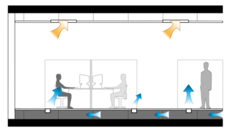
Underfloor air distribution (UFAD) is an air distribution strategy for providing ventilation and space conditioning in buildings as part of the design of a HVAC system. UFAD systems use an underfloor supply plenum located between the structural concrete slab and a raised floor system to supply conditioned air to supply outlets, located at or near floor level within the occupied space. Air returns from the room at ceiling level or the maximum allowable height above the occupied zone.

<span class="mw-page-title-main">Duct leakage testing</span>

A duct leakage tester is a diagnostic tool designed to measure the airtightness of forced air heating, ventilating and air-conditioning (HVAC) ductwork. A duct leakage tester consists of a calibrated fan for measuring an air flow rate and a pressure sensing device to measure the pressure created by the fan flow. The combination of pressure and fan flow measurements are used to determine the ductwork airtightness. The airtightness of ductwork is useful knowledge when trying to improve energy conservation.

Dynamic insulation is a form of insulation where cool outside air flowing through the thermal insulation in the envelope of a building will pick up heat from the insulation fibres. Buildings can be designed to exploit this to reduce the transmission heat loss (U-value) and to provide pre-warmed, draft free air to interior spaces. This is known as dynamic insulation since the U-value is no longer constant for a given wall or roof construction but varies with the speed of the air flowing through the insulation. Dynamic insulation is different from breathing walls. The positive aspects of dynamic insulation need to be weighed against the more conventional approach to building design which is to create an airtight envelope and provide appropriate ventilation using either natural ventilation or mechanical ventilation with heat recovery. The air-tight approach to building envelope design, unlike dynamic insulation, results in a building envelope that provides a consistent performance in terms of heat loss and risk of interstitial condensation that is independent of wind speed and direction. Under certain wind conditions a dynamically insulated building can have a higher heat transmission loss than an air-tight building with the same thickness of insulation. Often the air enters at about 15 °C.

Airflow, or air flow, is the movement of air. The primary cause of airflow is the existence of air. Air behaves in a fluid manner, meaning particles naturally flow from areas of higher pressure to those where the pressure is lower. Atmospheric air pressure is directly related to altitude, temperature, and composition.

<span class="mw-page-title-main">Air Infiltration and Ventilation Centre</span>

Air Infiltration and Ventilation Centre (AIVC) is the International Energy Agency information centre on energy efficient ventilation of buildings.

<span class="mw-page-title-main">TightVent Europe</span>

TightVent Europe is a platform focused on building and ductwork airtightness issues. The platform's creation was triggered to meet the 2020 targets of the Directive on the energy performance of buildings and overcome the challenges related to envelope and ductwork leakage towards the generalization of nearly zero-energy buildings. The platform's main activities include producing and disseminating policy-oriented publications, networking among local or national airtightness associations, and organizing conferences, workshops and webinars.

Ductwork airtightness can be defined as the resistance to inward or outward air leakage through the ductwork envelope. This air leakage is driven by differential pressures across the ductwork envelope due to the combined effects of stack and fan operation.

References

As of 5 February 2014, this article is derived in whole or in part from http://tightvent.eu/faqs . The copyright holder has licensed the content in a manner that permits reuse under CC BY-SA 3.0 and GFDL. All relevant terms must be followed.

  1. 1 2 3 G. Guyot, F. R. Carrié and P. Schild (2010). "Project ASIEPI – Stimulation of good building and ductwork airtightness through EPBD" (PDF).
  2. 1 2 M. Limb, "Technical note AIVC 36- Air Infiltration and Ventilation Glossary," International Energy Agency energy conservation in buildings and community systems programme, 1992
  3. Building Energy Codes, “Building Technologies Program: Air Leakage Guide”, U.S Department of Energy, September 2011
  4. U.S. Department of Energy, “enVerid Systems - HVAC Load Reduction”. Retrieved August 2018
  5. Bomberg, Mark; Kisilewicz, Tomasz; Nowak, Katarzyna (16 September 2015). "Is there an optimum range of airtightness for a building?". Journal of Building Physics. 39 (5): 395–421. doi:10.1177/1744259115603041. ISSN   1744-2591. S2CID   110837461.
  6. 1 2 D. Butler and A. Perry, "Co-heating Tests on BRE Test Houses Before and After Remedial Air Sealing," Building Research Establishment
  7. 1 2 R. Coxon, “Research into the effect of improving airtightness in a typical UK dwelling,” The REHVA European HVAC Journal-Special issue on airtightness, vol. 50, no. 1, pp. 24-27, 2013.
  8. M.H. Sherman and R. Chan, "Building Airtightness: Research and Practice", Lawrence Berkeley National Laboratory report NO. LBNL-53356, 2004
  9. 1 2 L. Mouradian and X. Boulanger, "QUAD-BBC, Indoor Air Quality and ventilation systems in low energy buildings," AIVC Newsletter No2, June 2012
  10. 1 2 TightVent Europe: Building and Ductwork Airitightness Platform, http://tightvent.eu/
  11. J.Langmans "Feasibility of exterior air barriers in timber frame construction", 2013
  12. F.R. Carrié, R. Jobert, V. Leprince: “Contributed report 14. Methods and techniques for airtight buildings”, Air Infiltration and Ventilation Centre, 2012
  13. 1 2 3 4 ISO Standard 9972, “Thermal Insulation-Determination of Building Air Tightness – Fan Pressurization Method”, International Standards Organization, 2006
  14. 1 2 3 4 EN 13829:2000, "Thermal performance of building - Determination of air permeability of buildings - Fan pressurization method (ISO 9972:1996, modified)", 2000
  15. ASHRE, "ASHRAE Handbook-Fundamentals" Atlanta, 2013
  16. R. Carrié & P. Wouters, "Technical note AIVC 67- Building airtightness: a critical review of testing, reporting and quality schemes in 10 countries," International Energy Agency energy conservation in buildings and community systems programme, 2012.
  17. ASTM, Standard E779-10, “Test Method for Determining Air Leakage by Fan Pressurization”, ASTM Book of Standards, American Society of Testing and Materials, Vol. 4 (11), 2010
  18. ASTM, Standard E1827-11, “Standard Test Methods for Determining Airtightness of Buildings Using an Orifice Blower Door”, ASTM Book of Standards, American Society of Testing and Materials, Vol. 4 (11), 2011.
  19. CAN/CGSB Standard 149, “Determination of the Airtightness of Building Envelopes by Fan Depressurization Method”, Canadian General Standards Board, 1986
  20. CAN/CGSB Standard 149.15-96, “Determination of the Overall Envelope Airtightness of Buildings by the Fan Pressurization Method Using the Building's Air Handling Systems”, Canadian General Standards Board, 1996
  21. R. Carrié, M. Kapsalaki and P. Wouters, "Right and Tight: What's new in Ductwork and Building Airtightness?," BUILD UP energy solutions for better buildings, 19 March 2013.
  22. International Code Council: "2012 International Energy Conservation Code", 2012
  23. U.S. Army Corps of Engineers & Air Barrier Association of America: "Air Leakage Test Protocol for Building Envelopes", 2012
  24. W. Anis : "The changing requirements of airtightness in the US", proceedings of the AIVC -TightVent Workshop: "Building & Ductwork airtightness: Design, Implementation, Control and Durability: Feedback from Practice and Perspectives", 18–19 April 2013