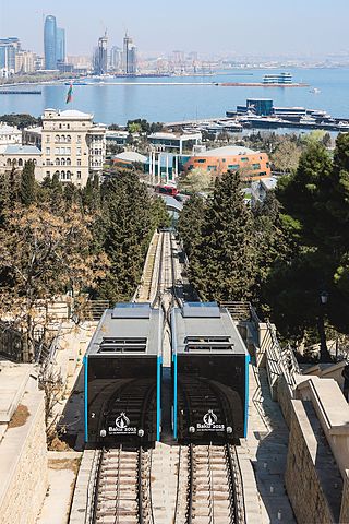
A funicular is a type of cable railway system that connects points along a railway track laid on a steep slope. The system is characterized by two counterbalanced carriages permanently attached to opposite ends of a haulage cable, which is looped over a pulley at the upper end of the track. The result of such a configuration is that the two carriages move synchronously: as one ascends, the other descends at an equal speed. This feature distinguishes funiculars from inclined elevators, which have a single car that is hauled uphill.

The Rimutaka Incline was a 3-mile-long (4.8 km), 3 ft 6 in gauge railway line on an average grade of 1-in-15 using the Fell system between Summit and Cross Creek stations on the Wairarapa side of the original Wairarapa Line in the Wairarapa district of New Zealand. The term "Rimutaka Incline" is sometimes used incorrectly to refer to other parts or all of the closed and deviated section of the Wairarapa Line between Upper Hutt and Speedy's Crossing, near Featherston. The incline formation is now part of the Remutaka Rail Trail.

The Cromford and High Peak Railway (C&HPR) was a standard-gauge line between the Cromford Canal wharf at High Peak Junction and the Peak Forest Canal at Whaley Bridge. The railway, which was completed in 1831, was built to carry minerals and goods through the hilly rural terrain of the Peak District within Derbyshire, England. The route was marked by a number of roped worked inclines. Due to falling traffic, the entire railway was closed by 1967.
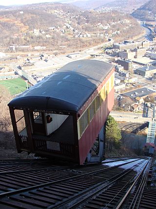
The Johnstown Inclined Plane is a 896.5-foot (273.3 m) funicular in Johnstown, Cambria County, in the U.S. state of Pennsylvania. The incline and its two stations connect the city of Johnstown, situated in a valley at the confluence of the Stonycreek and the Little Conemaugh rivers, to the borough of Westmont on Yoder Hill. The Johnstown Inclined Plane is billed as the "world's steepest vehicular inclined plane". It can carry automobiles and passengers, up or down a slope with a grade of 71.9%. The travel time between stations is 90 seconds.

The Hay Inclined Plane is a canal inclined plane in the Ironbridge Gorge in Shropshire, with a height of 207 feet (63 m). It was located at the end of the Shropshire Canal, part of a network of canals that linked the industrial region of east Shropshire with the River Severn. The inclined plane was in operation from 1793 to 1894. It can be visited as part of the Blists Hill Victorian Town and is also a waypoint on the South Telford Heritage Trail.

The Bowes Railway, built by George Stephenson in 1826, is the world's only operational preserved standard gauge cable railway system. It was built to transport coal from pits in Durham to boats on the River Tyne. The site is a scheduled monument. The railway is open every week on Thursday, Friday and Saturday as well as on a number of event days throughout the year.
A gravity railroad or gravity railway is a railroad on a slope that allows cars carrying minerals or passengers to coast down the slope by the force of gravity alone. The speed of the cars is controlled by a braking mechanism on one or more cars on the train. The cars are then hauled back up the slope using animal power, a locomotive or a stationary engine and a cable, a chain or one or more wide, flat iron bands. A much later example in California used 4 ft 8+1⁄2 instandard gauge steam engines to pull gravity cars back to the summit of Mt. Tamalpais.
A cable railway is a railway that uses a cable, rope or chain to haul trains. It is a specific type of cable transportation.

Until it closed in 1967 the Hopton Incline was the steepest stretch of conventional, adhesion-worked standard gauge railway running line in the UK. The incline was situated in sparsely populated, exposed limestone uplands in the Peak District of Derbyshire, England.

The Peak Forest Tramway was an early horse- and gravity-powered industrial railway system in Derbyshire, England. Opened for trade on 31 August 1796, it remained in operation until the 1920s. Much of the route and the structures associated with the line remain. The western section of the line is now the route of the Peak Forest Tramway Trail.
The Ballochney Railway was an early railway built near Airdrie, Lanarkshire, now in Monklands, Scotland. It was intended primarily to carry minerals from coal and ironstone pits, and stone quarries, in the area immediately north and east of Airdrie, to market, predominantly over the adjoining Monkland and Kirkintilloch Railway. Passengers were carried later.

The Shropshire Canal was a tub boat canal built to supply coal, ore and limestone to the industrial region of east Shropshire, England, that adjoined the River Severn at Coalbrookdale. It ran from a junction with the Donnington Wood Canal ascending the 316 yard long Wrockwardine Wood inclined plane to its summit level, it made a junction with the older Ketley Canal and at Southall Bank the Coalbrookdale (Horsehay) branch went to Brierly Hill above Coalbrookdale; the main line descended via the 600 yard long Windmill Incline and the 350 yard long Hay Inclined Plane to Coalport on the River Severn. The short section of the Shropshire Canal from the base of the Hay Inclined Plane to its junction with the River Severn is sometimes referred to as the Coalport Canal.
The Rosedale Railway was an 19.5-mile (31.4 km) goods-only railway line running from Battersby Junction via Ingleby Incline, across the heights of the North York Moors in North Yorkshire, England to reach iron ore deposits in the remote hills of the Rosedale valley. It opened to traffic as a narrow gauge railway to Ingleby Incline top in 1858, converted to standard gauge and opened to Rosedale West in 1861, and closed completely in 1929. Apart from Ingleby Incline, no major engineering works were constructed, and as such, particularly the east branch, the railway followed the contours of the surrounding hillside. The former trackbeds of the railway are in use by walkers and cyclists.
The Stanhope and Tyne Railway was an early British mineral railway, that ran from Stanhope in County Durham, to South Shields at the mouth of the River Tyne. The object was to convey limestone from Stanhope and coal from West Consett and elsewhere to the Tyne, and to local consumers. Passengers were later carried on parts of the line.

The Integral Coach Factory (ICF) coach was a conventional passenger coach used on the majority of main-line trains in India. The design of the coach was developed by Integral Coach Factory, Perambur, Chennai, India in collaboration with the Swiss Car & Elevator Manufacturing Co, Schlieren, Switzerland in the 1950s. The design is also called the Schlieren design based on the location of the Swiss company. The 1st ICF coach had been flagged by then Prime Minister Jawaharlal Nehru on 2 October 1955. The last ICF coach was flagged off by senior technician Shri Bhaskar P. in the presence of Railway Board Chairman Ashwani Lohani on 19 January 2018.

The yaw bearing is the most crucial and cost intensive component of a yaw system found on modern horizontal axis wind turbines. The yaw bearing must cope with enormous static and dynamic loads and moments during the wind turbine operation, and provide smooth rotation characteristics for the orientation of the nacelle under all weather conditions. It has also to be corrosion and wear resistant and extremely long lasting. It should last for the service life of the wind turbine) while being cost effective.
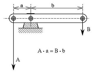
A simple machine that exhibits mechanical advantage is called a mechanical advantage device - e.g.:
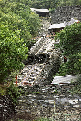
The car gwyllt is a Welsh invention used by quarrymen to ride downhill on the steep inclined planes of a slate quarry.
Several mineral railways were constructed around Dunfermline in western Fife, Scotland, in the eighteenth century and later. Their purpose was to convey minerals to market from the outcropping coal deposits that had encouraged industrial activity in the area from an early date.

Beckhole Incline was a steep, rope-worked gradient on the railway line between Whitby and Pickering, in the North Riding of Yorkshire, England. Opened in May 1836 as part of the horse-worked Whitby & Pickering Railway, the line was operated by three railway companies before becoming redundant on the opening of a diversionary line to the east that allowed through working by steam engines on the entire line. Although the incline was closed to regular traffic in 1865, it was used for a very brief period in 1872, to test a special locomotive intended for railways with steep gradients.
